CHAPTER 10 – PREVENTIVE AND CORRECTIVE MAINTENANCE 141
10.5.3 Serial communication interfaces
• AF 100 fieldbus - NAFA-01 installation and
start-up guide
• Modbus TCP - NETA-21 remote monitoring tool
user’s manual
• Modbus RTU - NMBA-01 installation and start-
up guide
• Profibus - NPBA-12 installation and start-up
guide
AF 100 interface
To identify the serial communication
interface in the drive, see the applicable
wiring diagrams. For further information
on the device, select the appropriate
manual:
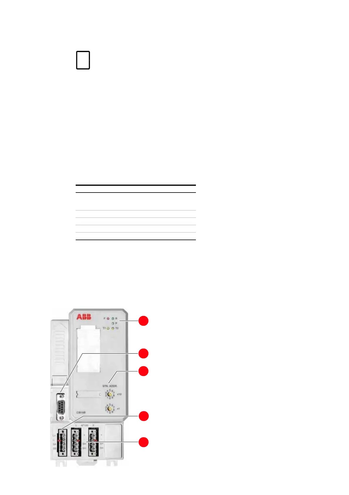
Table 10-1 AF 100 LED description
LED Meaning
F (Fault) Red Module fault. Also lights up during
module start-up. Turns off when
the self-test is successful
R (Run) Green In operation
P (Power OK) Green Internal power OK
T1 (Traffic 1) Yellow Data traffic on AF 100 cable 1
T2 (Traffic 2) Yellow Data traffic on AF 100 cable 2
1. Status LEDs
2. Service connector
3. AF 100 station address selectors
4. Power supply terminals
5. AF 100 terminals
5
4
3
2
1