CHAPTER 3 – CONTROL SYSTEM 57
Modbus TCP
Modbus RTU
Profibus
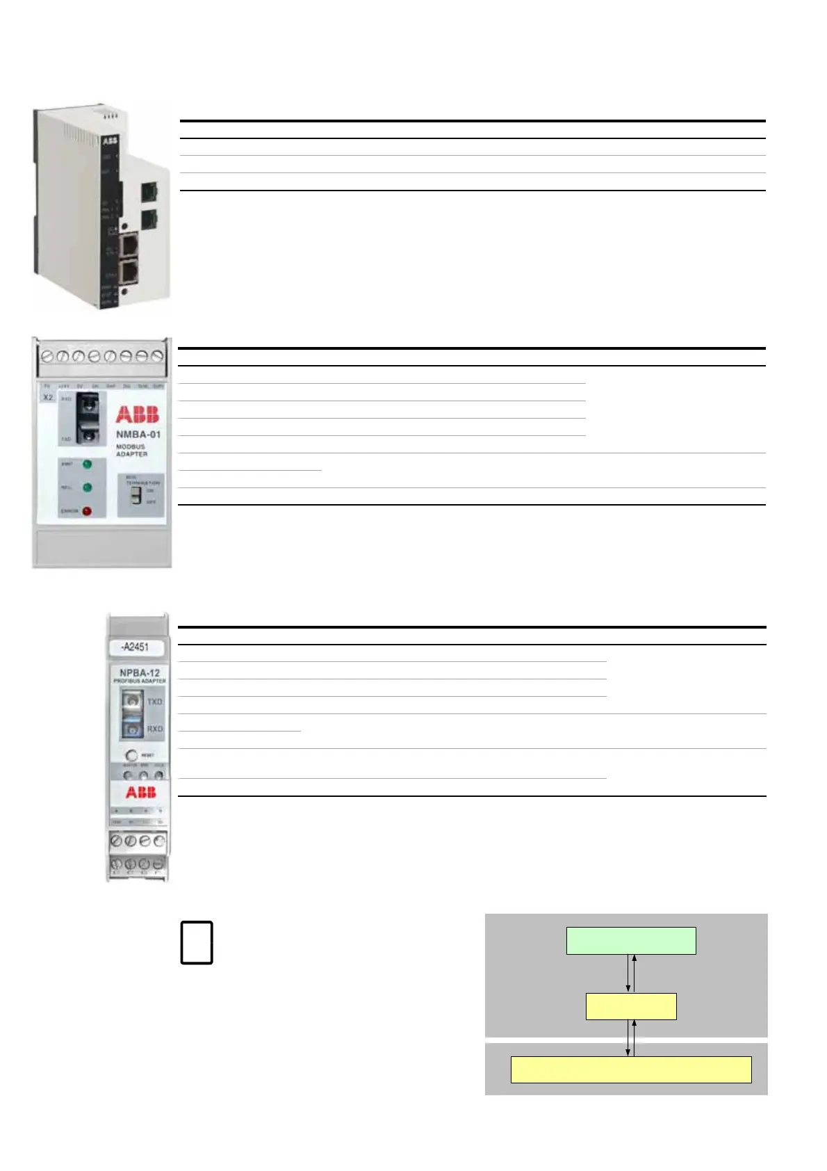
Communication with AMC circuit board
The fieldbus adapter is connected to channel 0 of
the AMC circuit board via optical fibers.
Terminal allocation
RJ-45 Ethernet connection
X1:1 +24 V (DC) supply
X1:2 0 V
Terminal allocation
X2:1 D(P) Data positive
Customer connections
X2:2 D(N) Data negative
X2:3 DG Data ground
X2:4 SHF Shield AC ground via RC filter
X2:5 SH Shield ground direct
X2:6 0 V Power supply (24 V (DC) +/- 10 %)
X2:7 +24 V
X2:8 PE Ground
NPBA-12 terminal assignment
X1:1 A Data negative (conductor 2 in twisted pair)
Customer connections
X1:2 B Data positive (conductor 1in twisted pair)
X1:3 A Data negative (conductor 2 in twisted pair)
X1:4 B Data positive (conductor 1in twisted pair)
X2:5 24 V
Power supply (24 VDC +/- 10 %)
X2:6 0 V
X2:7 DG Cable data ground (optional 3rd conductor)
Connected to module ground via a 1MOhm/15 nF RC network
Customer connections
X2:8 SH Cable shield. Internally connected to module
To identify the adapter type installed in
the drive, see wiring diagrams.
INU
AMC circuit board
Higher-level control system
Fieldbus
adapter
DDCS