58 ACS2000 DFE UM 3BHS360367 ZAB E01 REV. K
Location
The fieldbus adapter is DIN rail-mounted inside the
control compartment (3-8).
The indicated mounting position may vary depend-
ing on the number of optional devices on the swing
frame.
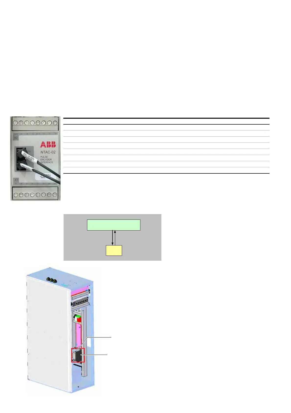
3.3.6 Pulse encoder interface NTAC (option)
Overview
In the following cases, a speed encoder is needed:
• If an immediate fly-start is required and there is
no time to scan the speed.
• If the application requires a speed accuracy of
0.5% of the nominal speed or better.
• If operation below 10% nominal speed is contin-
uous, which means more than a few seconds.
• If it is a master/follower application with
mechanically coupled machines.
In any other case, including constant torque appli-
cations, an encoder is not required..
Communication with AMC circuit board
The NTAC module communicates with the AMC cir-
cuit board of the INU via a fast optical link using
the standard DDCS protocol. The optical fibers are
connected to channel 1 of the AMC circuit board.
Location
The NTAC interface is DIN rail-mounted inside the
control compartment (3-8).
The indicated mounting position may vary depend-
ing on the number of optional devices on the swing
frame.
3.3.7 Motor temperature supervision
Motor temperature supervision is accomplished
via optional PT100 input modules. These modules
are suitable for connection of PT100 resistance
thermometers in accordance with IEC60751 in 2, 3
or 4 conductor systems.
3-8 Location of fieldbus
and pulse encoder
interface
Fieldbus adapter
Pulse encoder interface
Terminals X1 Terminals X2
1 A+ Channel A 1 -V 0 V
2A- 2-V 24 V
3 B+ Channel B 3 +V
4B- 424 / 25
5 Z+ Channel Z 5 15
6Z- 624
7SHShield 70 V
8SH 8+24 V
INU
AMC circuit board
DDCS
NTAC