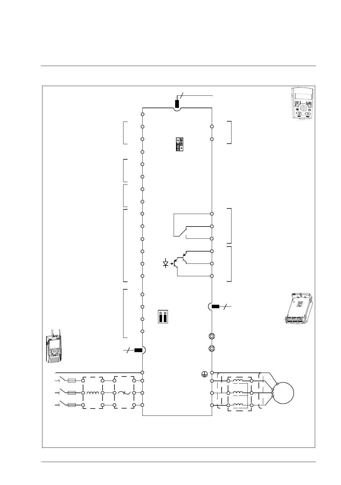
2. Hardware description
RONO
RONC
3
9
DI1
DI2
DI3
DI4
DI5
+24 V
Aux. voltage output
+24 V DC, max. 200 mA
DOSRC
GND
DCOM
DOOUT
DOGND
Digital/frequency output,
PNP transistor type
30 V DC, max. 100 mA
Relay output
250 V AC / 30 V DC / 6 A
V
mAGND
+10V
Reference voltage
+10 V DC, max. 10 mA
AI2
Analog input 2
GND
AI1
Analog input 1
0…10 V
SCR
Screen
Analog output
0…20 mA
AI1
AI2
*
)
Optional, not provided with the drive.
Note: For 1-phase power supply, connect power to U1/L and V1/N terminals.
EMC
VAR
EMC filter grounding screw
Varistor grounding screw
ROCOM
PROGRAMMABLE RELAY
AND DIGITAL OUTPUTS
Output relay
module MREL-01
11
17
18
19
20
21
22
AO 7
GND 8
12
13
14
15
16
10
6
5
1
2
SHIELD
B
A
GND_A
23
24
25
26
PROGRAMMABLE
DIGITAL INPUTS
4
FlashDrop
S1
J701
8
6
6
DI5 can also be used
as a frequency input
L1
L2
L3
PE
U1
V1
W1
PE
Input choke*
)
EMC filter*
)
3-phase
power supply
U2
V2
W2
AC motor
M
3 ~
Output choke*
)
Control panel (RJ-45)
EFB Comm port
Modbus RTU (EIA-485)
Johnson Controls N2
Siemens Building Technology
FLN (P1), BACnet (MS/TP)
200…480 V AC

 Loading...


