32 Mechanical installation
Mounting the drive on the wall
Units without vibration dampers
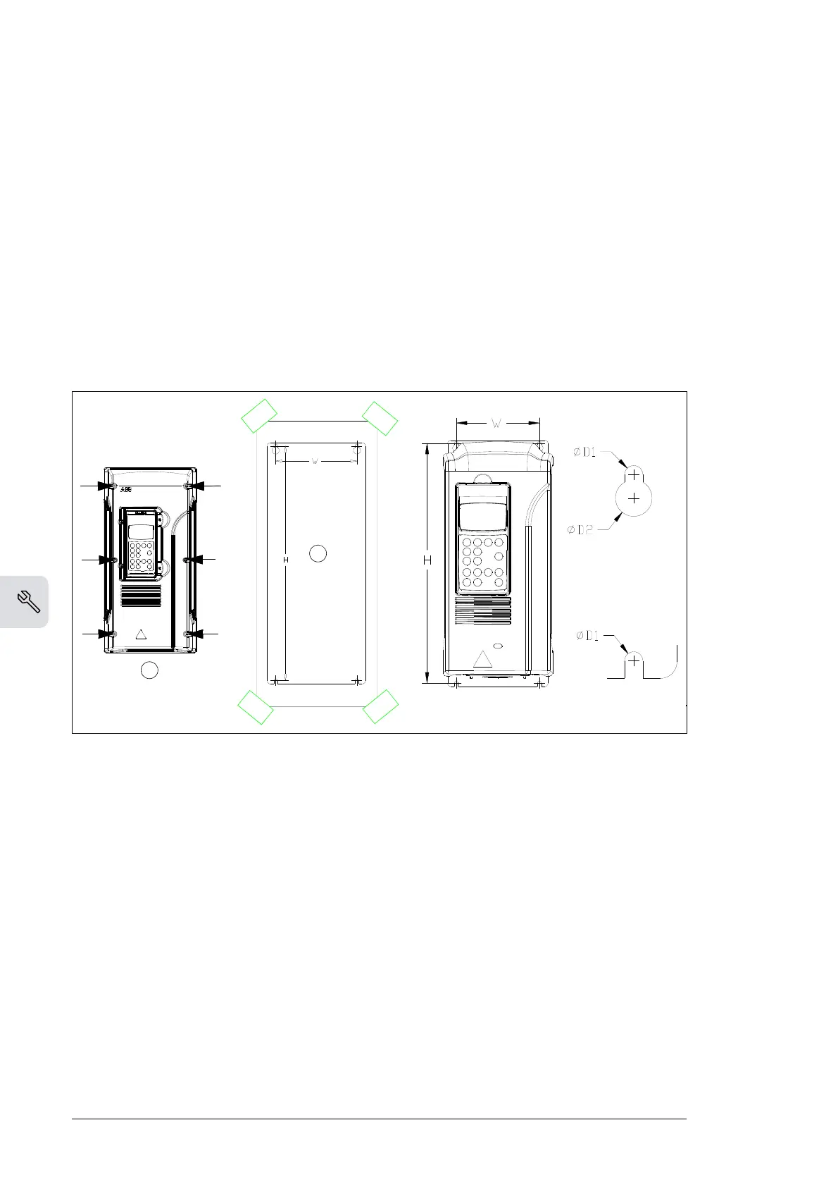
1. Mark the locations for the four holes. The mounting points are shown in
Dimensional drawings
(page 133). In frame sizes R2 to R5 (IP21, UL type 1), use
the mounting template on the package.
2. Install the screws or bolts in the marked locations.
3. IP55 (UL type 12) units: Remove the front cover.
4. Position the drive onto the screws on the wall. Note: Lift the drive by its chassis
(R6: by its lifting holes), not by its cover.
5. Tighten the screws in the wall.
IP55 (UL type 12) marine applications (+C132) of frame sizes R4 to
R6
See
ACS800-01/U1 Marine Supplement
[3AFE68291275 (English)].
Units with vibration dampers (+C131)
See
ACS800-01/U1 Vibration Damper Installation Guide
[3AFE68295351 (English)].
UL 12 units
Install the hood delivered with the drive 50 mm (2.0 in.) above the top of unit.