Parameters 191
10.99 RO/DIO control
word
Storage parameter for controlling the relay outputs and digital
input/outputs eg. through the embedded fieldbus interface.
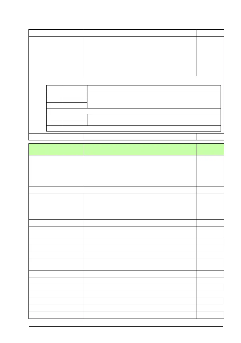
To control the relay outputs (RO) and the digital input/outputs
(DIO) of the drive, send a control word with the bit
assignments shown below as Modbus I/O data. Set the target
selection parameter of that particular data (58.101…58.124)
to RO/DIO control word. In the source selection parameter of
the desired output, select the appropriate bit of this word.
0000h
0000h…FFFFh RO/DIO control word. 1 = 1
11
11 Standard DIO, FI, FO
Configuration of digital input/outputs and frequency
inputs/outputs.
11.01 DIO status Displays the status of digital input/outputs DIO2 and DIO1.
The activation/deactivation delays (if any are specified) are
ignored. A filtering time (for input mode) can be defined by
parameter 10.51 DI filter time.
Example: 0010 = DIO2 is on, DIO1 is off.
This parameter is read-only.
-
0000b…0011b Status of digital input/outputs. 1 = 1
11.02 DIO delayed status Displays the delayed status of digital input/outputs DIO2 and
DIO1. This word is updated only after activation/deactivation
delays (if any are specified).
Example: 0010 = DIO2 is on, DIO1 is off.
This parameter is read-only.
-
0000b…0011b Delayed status of digital input/outputs. 1 = 1
11.05 DIO1 function Selects whether DIO1 is used as a digital output or input, or a
frequency input.
Output
Output DIO1 is used as a digital output. 0
Input DIO1 is used as a digital input. 1
Frequency DIO1 is used as a frequency input. 2
11.06 DIO1 output source Selects a drive signal to be connected to digital input/output
DIO1 when parameter 11.05 DIO1 function is set to Output.
Ready run
Not energized Output is off. 0
Energized Output is on. 1
Ready run Bit 1 of 06.11 Main status word (see page 166). 2
Enabled Bit 0 of 06.16 Drive status word 1 (see page 167). 4
Started Bit 5 of 06.16 Drive status word 1 (see page 167). 5
Magnetized Bit 1 of 06.17 Drive status word 2 (see page 168). 6
Running Bit 6 of 06.16 Drive status word 1 (see page 167). 7
No. Name/Value Description Def/FbEq16
Bit Name Description
0 RO1 Source bits for relay outputs RO1…RO3 (see parameters 10.24, 10.27 and
10.30).
1RO2
2RO3
3…7 Reserved
8 DIO1 Source bits for digital input/outputs DIO1…DIO3 (see parameters 11.0 6
and 11.10).
9DIO2
10…15 Reserved
 Loading...


