of the charging circuit can be different than shown in the figure. For a detailed description,
refer to the circuit diagrams delivered with the drive.
-S61-S61
-K640-K640
-A41
-T11.x
XSTO
XSTO
.OUT
2)
IN2
IN1
SGND
OUT
OUT1
SGND
OUT2
SGND
-X52B
-X51B
IN1
SGND
IN2
SGND
OUT1
SGND
OUT2
SGND
-A41
-T11.x
XSTO
XSTO
.OUT
2)
IN2
IN1
SGND
OUT
OUT1
SGND
OUT2
SGND
-X52B
-X51B
IN1
SGND
IN2
SGND
OUT1
SGND
OUT2
SGND
-A640-A640
-A51
DIIL
24 VDC
-A51
DIIL
24 VDC
-A640
-A51
DIIL
24 VDC
-K640-K640
-Q4-Q4
230 VAC
-K640-K640
-Qx-Qx
1)
-A640
-S62-S62
+24 VDC
-Qx
~
-T01
-Q4
~~
-T11
M
3~
M
3~
~
-T11
M
3~
-Qx
~
-T01
-Q4
~
-T11
M
3~
-S62-S62
-Q4-Q4
QxQx
3)
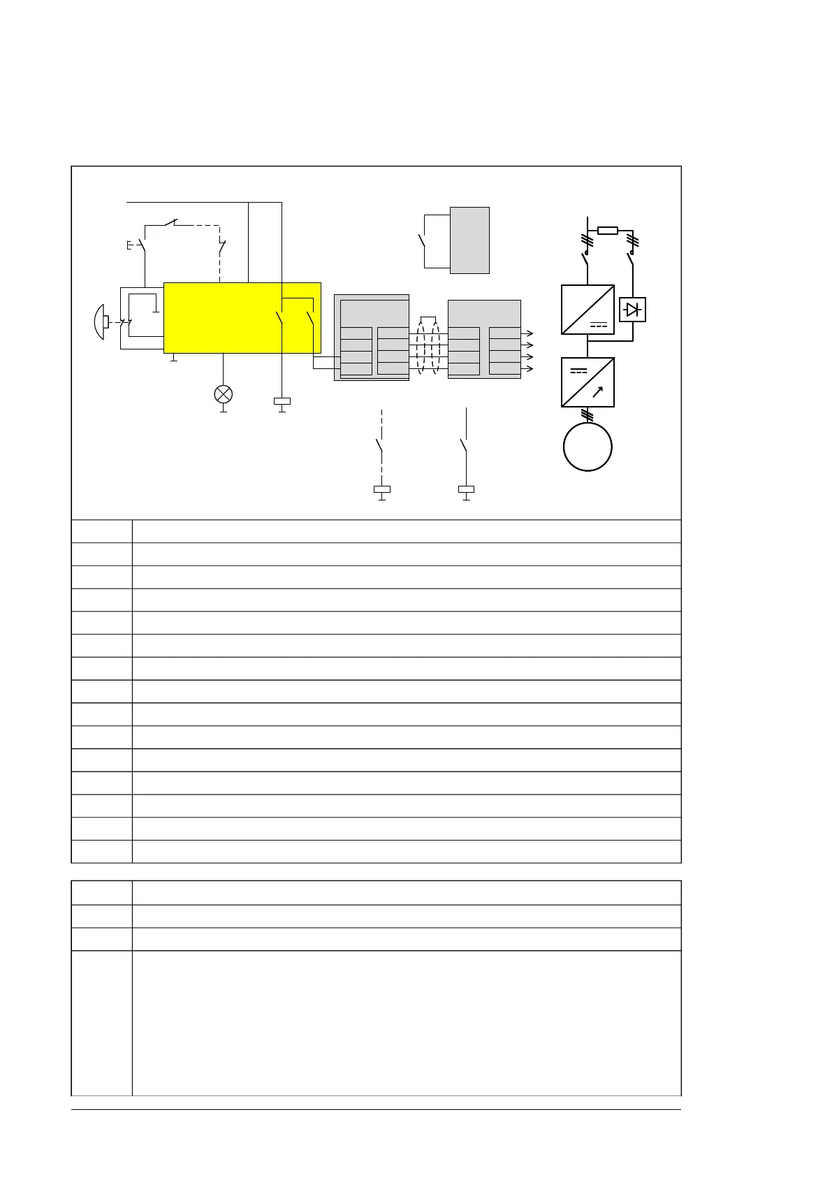
The dashed line in the figure shows a user-defined installation.- - -
Inverter control unitA41
Supply control unitA51
Emergency stop safety relayA640
Safety relayK640
Emergency stop buttonS61
Emergency stop reset button with indicator lightS62
Main contactor/breaker (user-defined)Qx
Charging contactor (option +F272)Q4
Supply unitT01
Inverter unit which contains inverter module(s)T11
Inverter moduleT11.x
Supply voltage for main contactor/breaker control (user-defined)1)
Connection to parallel inverter modules (if any)2)
Main circuit3)
OperationStep
Initial status: The drive is in operation and the motor is running.
The user pushes the emergency stop button [S61]. This activates the emergency stop function.1
The emergency stop safety relay [A640] de-energizes XSTO inputs IN1 and IN2 of the inverter
control unit [A41]. This activates the inverter unit Safe torque off function.
2
The emergency stop safety relay [A640] de-energizes the DIIL input on the supply control unit [A51].
This gives the emergency stop command to the supply unit.
The emergency stop safety relay [A640] de-energizes the safety relay [K640].
The safety relay [K640] opens the main contactor/breaker [Qx], which disconnects the input power
from the supply unit [T01].
The charging contactor [Q4] is opened, if the emergency stop is activated during charging.
16 Option description

 Loading...


