Installation, Operations and Maintenance Manual
6
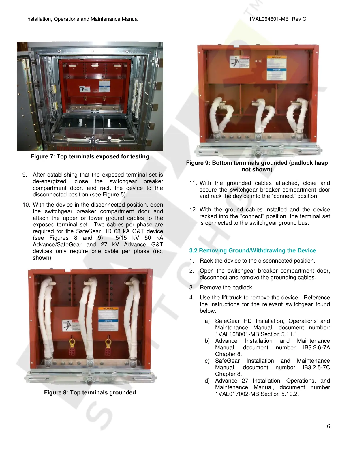
Figure 7: Top terminals exposed for testing
9. After establishing that the exposed terminal set is
de-energized, close the switchgear breaker
compartment door, and rack the device to the
disconnected position (see Figure 5).
10. With the device in the disconnected position, open
the switchgear breaker compartment door and
attach the upper or lower ground cables to the
exposed terminal set. Two cables per phase are
required for the SafeGear HD 63 kA G&T device
(see Figures 8 and 9). 5/15 kV 50 kA
Advance/SafeGear and 27 kV Advance G&T
devices only require one cable per phase (not
shown).
Figure 8: Top terminals grounded
Figure 9: Bottom terminals grounded (padlock hasp
not shown)
11. With the grounded cables attached, close and
secure the switchgear breaker compartment door
and rack the device into the “connect” position.
12. With the ground cables installed and the device
racked into the “connect” position, the terminal set
is connected to the switchgear ground bus.
3.2 Removing Ground/Withdrawing the Device
1. Rack the device to the disconnected position.
2. Open the switchgear breaker compartment door,
disconnect and remove the grounding cables.
3. Remove the padlock.
4. Use the lift truck to remove the device. Reference
the instructions for the relevant switchgear found
below:
a) SafeGear HD Installation, Operations and
Maintenance Manual, document number:
1VAL108001-MB Section 5.11.1.
b) Advance Installation and Maintenance
Manual, document number IB3.2.6-7A
Chapter 8.
c) SafeGear Installation and Maintenance
Manual, document number IB3.2.5-7C
Chapter 8.
d) Advance 27 Installation, Operations, and
Maintenance Manual, document number
1VAL017002-MB Section 5.10.2.
Courtesy of NationalSwitchgear.com