17
1VAL050601-MB Rev C
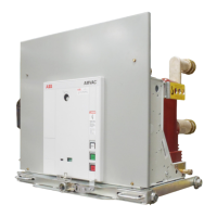
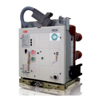
STRUCTURE AND FUNCTION
Figure 2a: Circuit breaker front with controls
1 Breaker enclosure
1.1 Front Plate
1.2 Lifting bracket, both sides
2 “Ready” indicator
3 CLOSE push-button
4 OPEN push-button
5 Mechanical operating cycle counter
6 Mechanical CLOSE/OPEN indicator
7 Rating plate
8 Socket for emergency open operation
lever
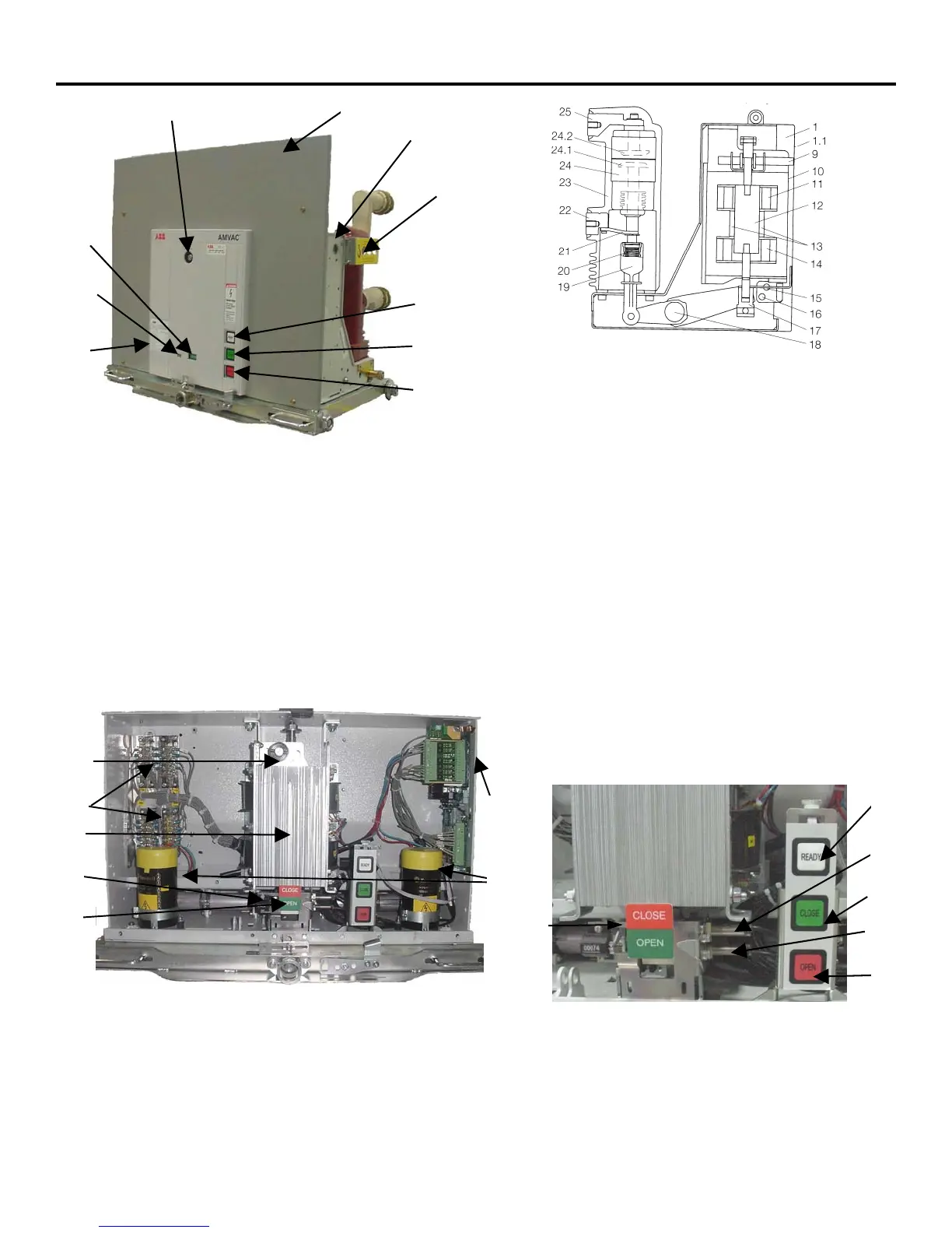
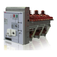
Figure 2b: Sectional view of a circuit breaker type,
AMVAC schematic diagram
1 Circuit breaker enclosure
1.1 Front panel, removable
9 Emergency manual opening
mechanism
10 Magnetic actuator
11 OPEN coil
12 Magnet armature
13 Permanent magnets
14 CLOSE coil
17 Stroke adjuster
18 Lever shaft
19 Insulated link rod
20 Contact force spring
21 Flexible connector
22 Lower breaker terminal
23 Cast insulation
24 Vacuum interrupter
24.1 Moving Contact
24.2 Fixed Contact
25 Upper breaker terminal
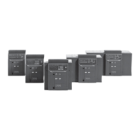
Figure 2c: View of the magnetic actuator mechanism and
auxiliary systems with the front cover removed
5 Mechanical operating cycle counter
6 Mechanical switch position indicator
10 Actuator
26 Storage Capacitors
27 Circuit breaker control unit (ED2 board)
28 Auxiliary switches
7
5
6
2
3
4
1.2
1.1
1
8
8
10
5
6
27
28
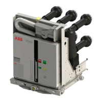
Figure 2d: Switch position indicator
6 Mechanical switch position indicator
15 Sensor for “Circuit-breaker OPEN” signal
16 Sensor for “Circuit-breaker CLOSED”
signal
6
15
16
2
3
4
26
Provided by Northeast Power Systems, Inc. (NEPSI)