33
1VAL050601-MB Rev C
APPENDIX C
ED2 ELECTRONIC CONTROL BOARD
APPENDIX C
Following are the basic characteristics for the control power and close and open operations of the AMVAC
TM
circuit
breaker.
DRAWOUT - STANDARD WIRING:
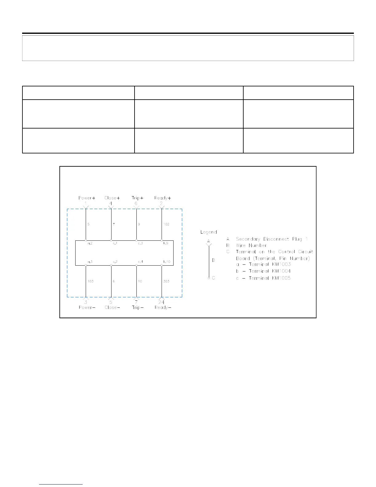
The schematic illustrates the basic wiring scheme for a drawout circuit breaker with standard wiring.
The point-to-point diagram illustrates the physical connections and wire numbers used in the wiring harness.
FIXED-MOUNT - STANDARD WIRING:
The wiring scheme for the fixed-mount circuit breakers is exactly the same except that there is no pin monitor/close
blocker switch so these connections are the same as if the switch in the truck is always closed. Also fixed mount break-
ers will come with 5 feet length of secondary wiring.
Principal Connection Points
Control Circuit Board
CONTROL RANGE LOW VOLTAGE UNIT HIGH VOLTAGE UNIT
Binary Inputs AC or DC KM1005
1,2
(Includes Trip and Close)
21V to 264V Opening command can
go as low as 16.8V
21V to 264V Opening command can
go as low as 16.8V
Auxiliary Power
AC or DC — KM1003
1
20-75VDC, 23-50 VAC 77-280VDC, 85-264 VAC
Provided by Northeast Power Systems, Inc. (NEPSI)