4
B – Panel-Mount AX400 Series Analyzers
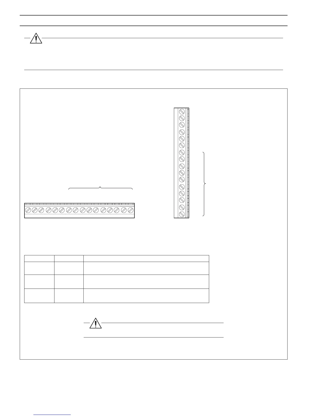
Terminal Block C
(Profibus-DP Enabled Option Board)
Terminal Block C
(Profibus-DP Enabled Option Board)
A – Wall- /Pipe-Mount AX400 Series Analyzers
C1 Not used
C2 Not used
C3 PROFIBUS-DP Data Cable B – Red
C4 PROFIBUS-DP Data Cable A – Green
C5 PROFIBUS-DP Data Cable – Braided Screen
C6 Not Used
C7
C8
C9
C10
C11
See User Guide
C12
C13
C14
C15
C16
C1 Not used
C2 Not used
C3 PROFIBUS-DP Data Cable B – Red
C4 PROFIBUS-DP Data Cable A – Green
C5 PROFIBUS-DP Data Cable Braided Screen
C6 Not Used
C7
C8
C9
C10
C11
See User Guide
C12
C13
C14
C15
C16
PROFIBUS-DP Data Cable
Data Signal Cable Color Description
A Green Negative data line. Connect to pin 8 on Profibus-DP equipment
with 9-way D-type connectors
B Red Positive data line. Connect to pin 3 on Profibus-DP equipment
with 9-way D-type connectors
Braided N/A Cable screen. Usually connected to the D-type shell or pin 1 on
Screen Profibus-DP equipment with 9-way D-type connectors
Warning. Before making any electrical connections,
refer to the Warnings in Section 6 of the relevant User Guide.
Fig. 3.1 Network Cable Connection
3 NETWORK CONNECTION AND CONFIGURATION
Warnings. When connecting a PROFIBUS-enabled AX400 Series analyzer to a PROFIBUS-DP network:
• Use shielded data lines and ensure they are not reversed.
• Ensure all data lines are routed clear of the source of any strong electrical and magnetic fields.
• Refer to the relevant User Guide for all other installation and connection details.
3.1 Network Connections – Fig. 3.1

 Loading...


