CoriolisMaster FCB400, FCH400 CORIOLIS MASS FLOWMETER | OI/FCB400/FCH400-EN REV. E 49
… 7 Electrical connections
Electrical data for inputs and outputs
Note
When using the device in potentially explosive atmospheres,
note the additional temperature data in Use in potentially
explosive atmospheres on page 6!
Power supply L / N, 1+ / 2−
AC voltage
Terminals L / N
Operating voltage 100 to 240 V AC, 50 / 60 Hz
Power consumption < 20 VA
DC voltage
Terminals 1+ / 2−
Operating voltage 11 to 30 V DC
Power consumption 20 W
Current output 32 / Uco, 31 / 32 (basic device)
Can be configured for outputting mass flow, volume flow,
density and temperature via on-site software.
G11596-02
+
-
AB
IE
32-
Uco
32-
IE
31+
R
B
R
B
Uq
31+
Uco
+
-
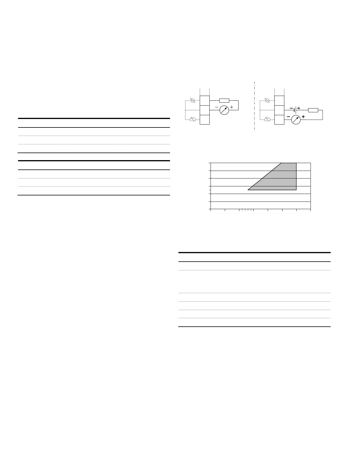
A Current output 31 / Uco, active B Current output 31 / 32 passive
Figure 31: (I = internal, E = external, R
B
= load)
G10323-02
0
0
100
200
300
400
500
600
5101520253035
RB [Ω]
Uq [V]
Permissible source voltage U
q
for passive outputs in relation to load
resistance R
B
where I
max
= 22 mA. = Permissible range
Figure 32: Source voltage for passive outputs
Current output Active Passive
Terminals Uco / 32 31 / 32
Output signal 4 to 20 mA or
4 to 12 to 20 mA
switchable
4 to 20 mA
Load R
B
250 Ω ≤ R
B
≤ 300 Ω 250 Ω ≤ R
B
≤ 600 Ω
Source voltage U
q
* – 13 V ≤ U
q
≤ 30 V
Measuring error < 0.1 % of measured value
Resolution 0.4 µA per digit
* The source voltage U
q
is dependent of the load R
B
and must be placed in an
additional area.
For information on communication via the HART protocol, refer
to HART® Communication on page 61.

 Loading...


