13
Alignment of
direct coupled
machines
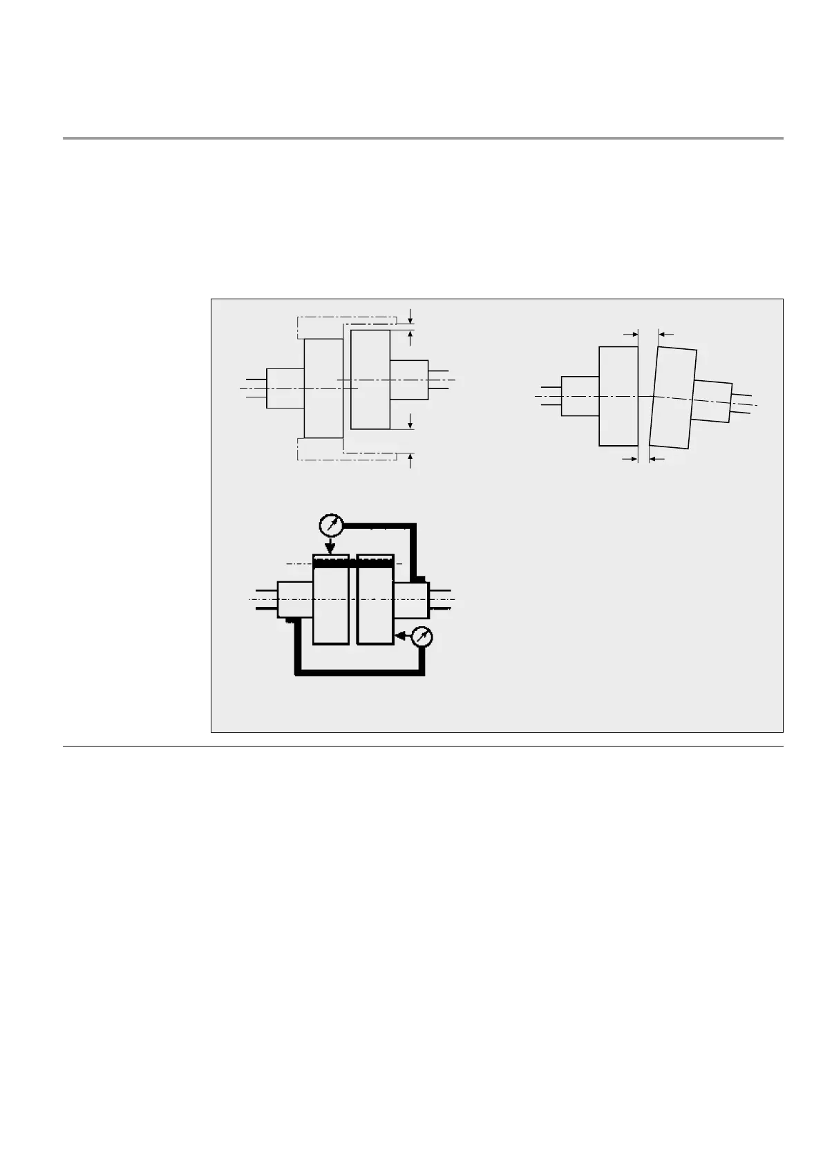
Good alignment ensures safe operation and long
machine life. Check the misalignment between the
coupling flanges after the machine has been in-
stalled. Maximum deviations, see fig. 3 and 4.
A common method is the use of dial indicators,
which are mounted according to fig. 5.
Machine alignment must be continued until dial
indicator readings of max. 0,05 mm are obtained.
To ensure correct alignment of the machine,
place suitable metal shims between machine feet
and mounting blocks. Installation instructions
from the suppliers of pumps, gear drives, etc. of-
ten specify the vertical and lateral displacement
of the driving shaft at operating temperature. It
is important that these instructions are observed
during alignment in order to avoid vibrations and
other disturbances during operation.
Fig. 3 Parallel alignment. A-B = max. 0.05 mm. Fig. 4 Angular alignment. A-B = max. 0.05 mm.
Fig. 5 Dial indicator for proper machine alignment.
Machine installation