68 EasyLine EL3000 Series Commissioning Instructions
Installing the Gas Analyzer
ATTENTION
The installation site must be stable enough to bear the weight (see
page 17) of the gas analyzer!
The 19-inch housing must be supported in the cabinet or the rack with
mounting rails!
Requisite material (not supplied)
19-inch Case (Model EL3020)
4 oval head screws (Recommendation: M6; this depends on the
cabinet/rack system)
1 pair of mounting rails (Design depends on the cabinet/rack system),
length approx. 240 mm corresponding to approx. 2/3 of the case
depth
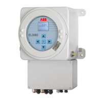
Wall-mounting Case (Model EL3040)
4 screws M8 or M10
Installing the Gas Analyzer
Install the gas analyzer in the cabinet/rack or on the wall.
Refer to the dimensional drawings.
Mount several 19-inch housings with a minimum spacing of 1 height unit
between housings.
Special Requirements for the Fidas24 Gas Analyzer
If the gas analyzer is installed in a closed cabinet, adequate ventilation of
the cabinet must be provided (at least 1 change of air per hour).
Special Requirements for the Gas Analyzer Model EL3020 for the Measurement
of Flammable Gases
An unimpeded exchange of air with the surroundings must be possible
around the gas analyzer from beneath (base plate) and from behind (gas
connections). The gas analyzer must not be put directly on a table. The
case apertures must not be closed. The distance to adjacent, built-in
components on the side must be at least 3 cm.
For installations in a closed cabinet, the cabinet must have adequate
ventilation (at least 1 air change per hour). The distance to adjacent, built-
in components underneath (floor plate) and behind (gas connections)
must be at least 3 cm.
Special Requirements for the Gas Analyzer Model EL3040 in Degree of
Protection II 3G
Due to the low mechanical stability of the display window, the gas
analyzer has to be installed and operated in such a way that mechanical
damage to the display window is ruled out.