Installing the Gas Analyzer 83
Electrical Connections
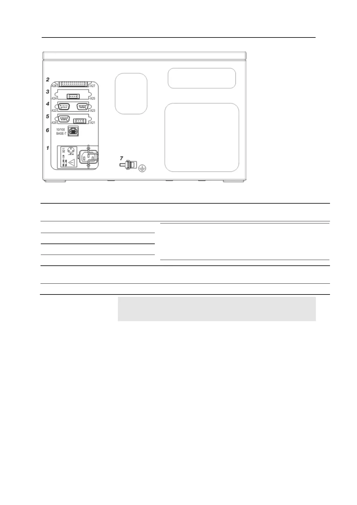
1
Power supply connection (see page 90) (3-pole grounded-instrument connector to EN 60320-1/C14,
mains le
ad supplied)
2
Digital I/O module (see page 85)
3
Analog output module (see page 84)
4
Modbus module (see page 87)
5
Profibus module (see page 88)
NOTE
The illustration shows all the available I/O module types and
only represents an example of the I/O modules equipment
(max. 4). The actual equipment of the supplied gas analyzer
can differ; it is documented in the analyzer data sheet.
6
Ethernet-10/100BASE-T interface (for configuration and software update and for transmission of the
QAL3 data)
7
Connection for equipotential bonding (see page 90) (capacity of terminal max. 4 mm
2
)
ATTENTION
Follow all applicable national safety regulations for the installation and
operation of electrical devices!
 Loading...