f
p
p
g
X
Y
96
100
3
c
a
36
225
50
(195)
160
35
22
48
96
25
5
L 9 x 19
ø 5
H
L
25
B
B
32
321±1,5
73±4
321±1,5
5
95±4
R 233
20
15
45+2
3
5
,5
°
87
29
40
58
90
S
SE
SE
0
C
S
B - B
40
E
: GCE7003225P0101
20
9
170
32 32
ø 13 / 13,5
68
19
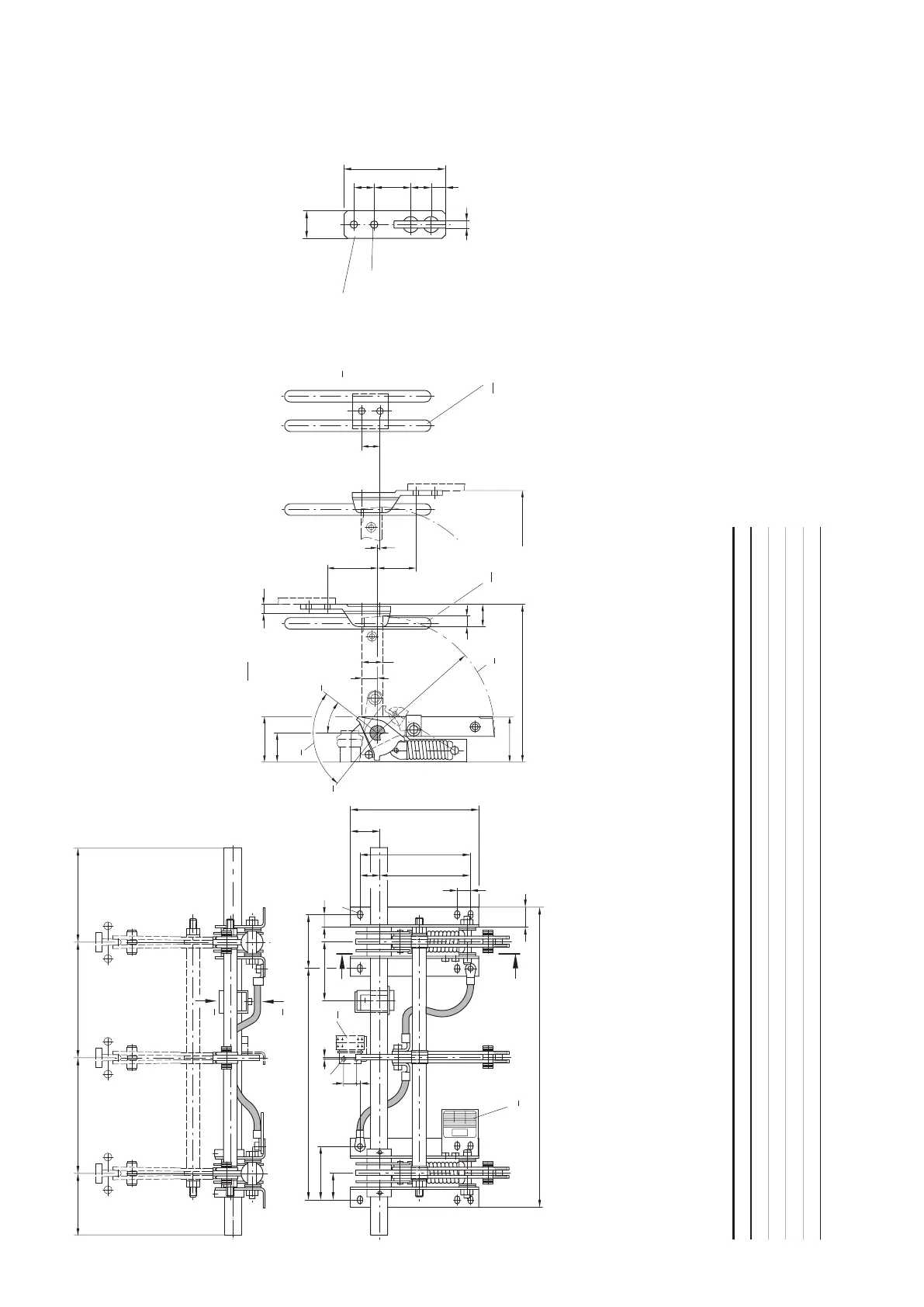
E = Earthing contact, H = Auxiliary switch, L = Rating plate,
SE = Control electrode varies with panel design,
X = View direction for switch position indicator,
Y = view direction for switch position indicator,
S = Operating/Switching angle, C = ON, O = OFF
• See dimensional drawing GCEM 360 524,
sheet 1, for shaft profi le
Caution:
Observe the notes in section rules for installation.
Contact blade distance: 8 ± 0,3 mm
Contact thickness: 9 mm
Contact force: 353 N
Contact spring force (cup springs): 376 N
Operating angle: 90
Switching angle: 90
Part number Type p a c g f Md OFF Md ON Weight kg
1) including earthing contact (Weight 3 Pieces: 1,8 kg)
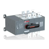
Earthing switch EK6
24 kV-Types
Dimensional drawing
GCEM700092, Sheet 5