Start-up
To control the drive with the adapter module, set at least the basic parameters listed in the table
below. For full parameter descriptions, refer to the adapter module’s user manual or to the drive’s
firmware manual.
Basic parameter settings
To take the settings into use, validate and refresh the parameters with parameter 51.27 FBA par
refresh.
Further information
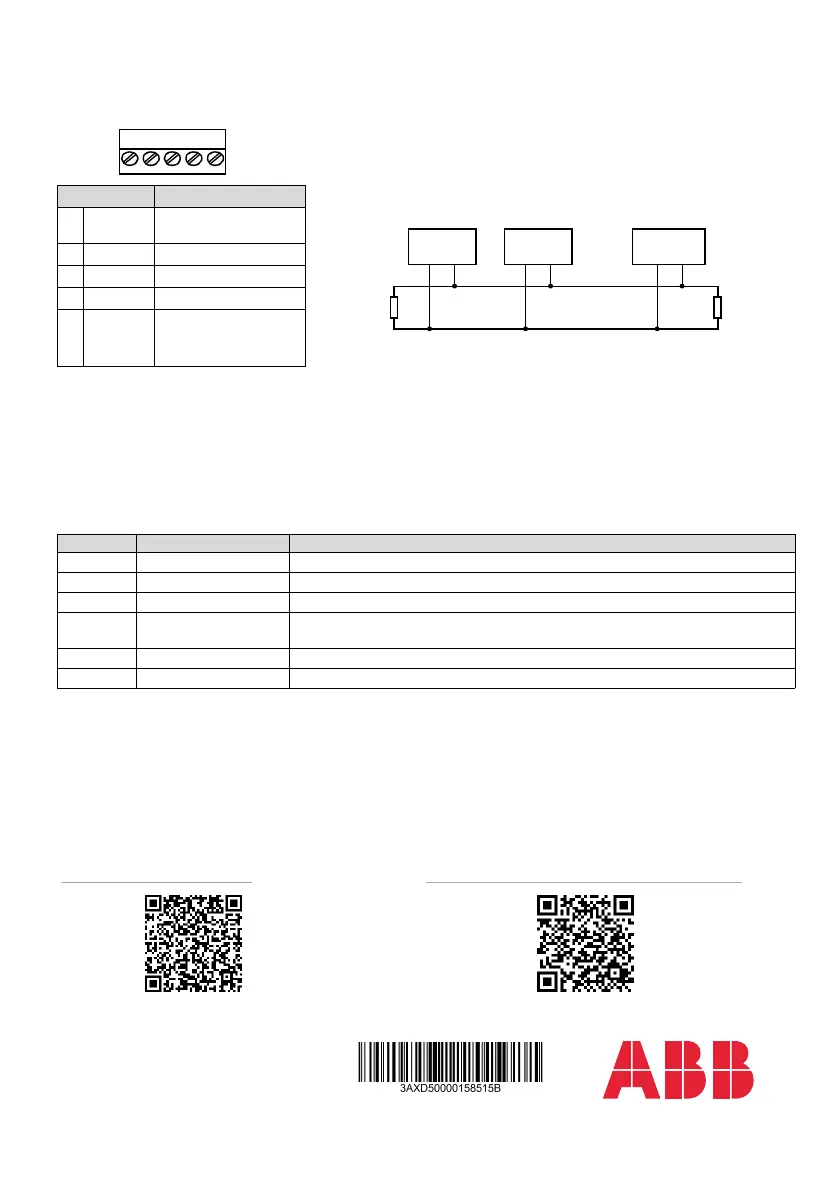
Pin allocation for [X1] Bus termination
The module does not provide bus termination. The DeviceNet
network should be terminated at both ends of the trunk cable with a
121 ohm, ¼ W, 1% metal film resistor.
Connect the resistor between the two signal wires (CAN_H, CAN_L)
on the DeviceNet cable, as shown in this figure
.
Pin Description
1 V- Network power supply
ground (0V DC)
2 CAN_L CAN_L bus line
3 SHLD Network cable shield
4CAN_H CAN_H bus line
5 V+ Network power supply
source (24V DC)
Index Name Value
20.01 Ext1 commands Fieldbus A
22.11 Speed ref1 source FBA A ref 1
28.11 Frequency ref1 source FBA A ref 1
50.01 FBA A enable Enable (or select the option slot in which the module is installed).
This activates the communication module. The HOST LED becomes green.
50.02 FBA A comm loss func Fault
51.02 MAC ID Set the MAC ID number for the drive.
See the latest version of FDNA-01 DeviceNet adapter module
user's manual (3AFE68573360 [English]) in ABB library
(www.abb.com/drives/documents).
For more information on ABB fieldbus options and protocols,
see the fieldbus communications web page
(new.abb.com/drives/connectivity/fieldbus-connectivity).
Node 1 Node n
121
CAN_H
CAN_L
Scanner
121
1%
Metal Film
1/4 W
1%
Metal Film
1/4 W
…
Fieldbus communications web
page
© Copyright 2023 ABB. All rights reserved.
Specifications subject to change without notice.
3AXD50000158515 Rev B (EN) 2023-01-25
abb.com/drives