10
1
2
3
4
56
7
8
6. Istruzioni per la manovra
dell'interruttore
6.1. Indicazioni di sicurezza
Gli interruttori HD4-HXA garantiscono un grado di
protezione minimo IP2X se installati nelle seguenti
condizioni:
– versione fissa, con rete di protezione
– versione estraibile, installati in quadro.
In tali condizioni l'operatore è assolutamente garan-
tito dall'accidentale contatto con parti in movimento.
Qualora vengano effettuate manovre meccaniche
sull'interruttore al di fuori del quadro o con reti di
protezioni rimosse, prestare la massima attenzione
alle parti in movimento.
Se le manovre risultassero impedite non forzare gli
interblocchi meccanici e verificare la correttezza
della sequenza delle manovre.
L'inserimento e l'estrazione dell'interruttore nei qua-
dri deve essere graduale per evitare urti che posso-
no deformare gli interblocchi meccanici.
!
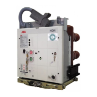
Fig. 6
Organi di manovra e segnalazione.
Operating and signalling parts.
Legenda
1 Segnalatore stato della pres-
sione SF6 (a richiesta)
2 Pulsante di apertura
3 Pulsante di chiusura
4 Contamanovre
5 Segnalatore interruttore aper-
to/chiuso
6 Albero per la carica manuale
delle mole di chiusura
7 Segnalatore molle di chiusura
cariche/scariche
8 Tasto di ripristino dell'interrut-
tore di protezione del motori-
duttore (a richiesta)
6. Instructions for circuit-breaker
operation
6.1. Safety indications
HD4-HXA circuit-breakers ensure a minimum degree
of protection IP2X if installed under the following
conditions:
– fixed version, with protection netting
– withdrawable version, installed in a switchboard.
Under these conditions, the operator is fully guaran-
teed against accidental contact with moving parts.
Should any mechanical operations be carried out on
the circuit-breaker outside the switchboard or with
the protection netting removed, be very careful of
any moving parts.
If the operations are prevented, do not force the
mechanical interlocks and check that the operation
sequence is correct.
The racking-in and racking-out operations of the
circuit-breaker must be carried out gradually to pre-
vent any impacts which might deform the mechani-
cal interlocks.
!
Caption
1 Signalling device for state of
SF6 pressure (on request)
2 Opening push button
3 Closing push button
4 Operator counter
5 Resetting button for protection
circuit-breaker of geared motor
(on request)
6 Shaft for manual closing spring
charging
7 Signalling device for closing
springs charged/discharged
8 Signalling device for circuit-
breaker open/closed
6.2. Organi di manovra e segnalazione
6.2. Operating and signalling parts