19 ELECTRONIC COMPACT STARTER | MANUAL
DOL- type
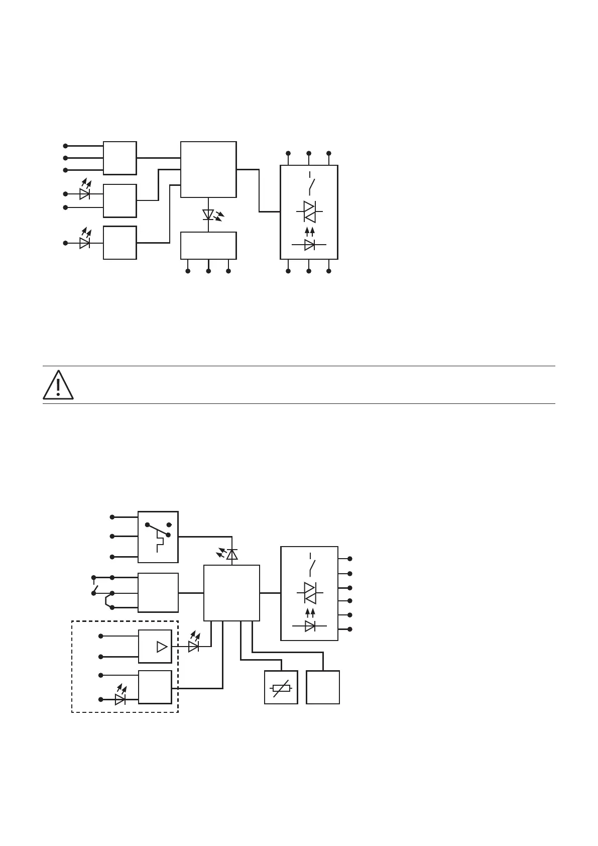
The HMI of the DOL device is described in chapter 1.9.1. The following figure 10 shows the corresponding drawing for the
device.
—
10 Circuit diagram of DOL
DOLE- type
For applications in explosion-protection areas, automatic restart is not permitted!
• If the 'Automatic RESET' mode is used, the load is switched on again after the cooling time of 20 min. has elapsed – if a con-
trol signal is still present.
The HMI of the DOLE device is described in chapter 1.9.2. The following figure 11 shows the corresponding drawing for the
device. The main difference to DOL-types is the connection point ⊥E. This is one possible connection point for the safety
relay Sentry SSR10/USR10 for emergency stop application.
—
11 Circuit diagram of DOLE types
1/L1 3/L2 5/L3
2/T1 4/T2 6/T3
& Error
Logic
µP
97 96 95
RES
MAN
RES
AUT
U
S
Ʇ
ON
MAN
RES
AUT
RESET 2
1/L1
3/L2
5/L3
2/T1
4/T2
6/T3
Logic
µP
U
S
Ʇ
ON
Reset24 V DC
ꞱE
U
S
24 V DC
RESET
AUTORESET
97
96
95
& Error
96/98 97
95
 Loading...