43 ELECTRONIC COMPACT STARTER | MANUAL
This is a product for environment A (industry). The device can cause unwanted radio interference if used in
domestic class B environments. In this case, the user may be obligated to take the necessary precautionary
measures.
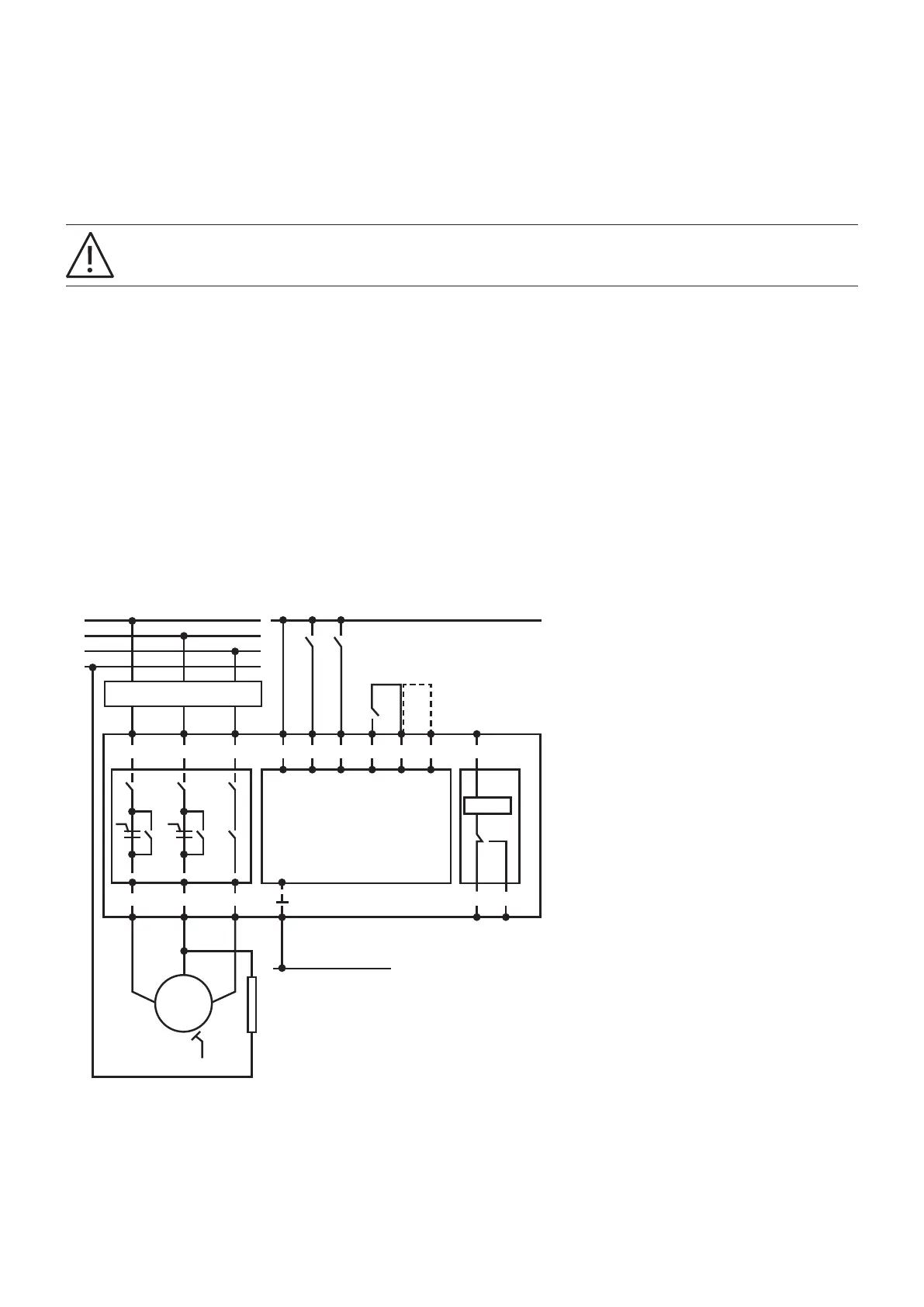
Auxiliary relays
Auxiliary relays for activating external brakes or acknowledgements, e.g. to the PLC, must be connected between 4/T2 and N
connections of the system.
—
7.1 Motors with a 230 V AC brake
A 230 V AC brake must be connected to the 4/T2 terminals and the star point of the motor. The current for braking is taken
from one phase and the neutral conductor, see figure 27, which is valid for the following types:
• DOL- types
• ROL- types
• R- type
The motor current monitoring must be increased by the brake value (nominal value of the brake). This has to be set at the
electronic compact starter. For setting the nominal current, please refer to chapter 3.3.
—
27 Commissioning a motor with a 230 V AC brake
—
7 Circuits with brakes
µController
M
3 ~
R MAN RES AUT 96
Signal
95 97
1/L1 3/L2 5/L3
2/T1 4/T2 6/T3
Device and wire protection
U
S
U1
V1
PE
W1
∆∇ ∆∇
+ 24 V DC
L1
L2
L3
N
0 V DC
L