21 ELECTRONIC COMPACT STARTER | MANUAL
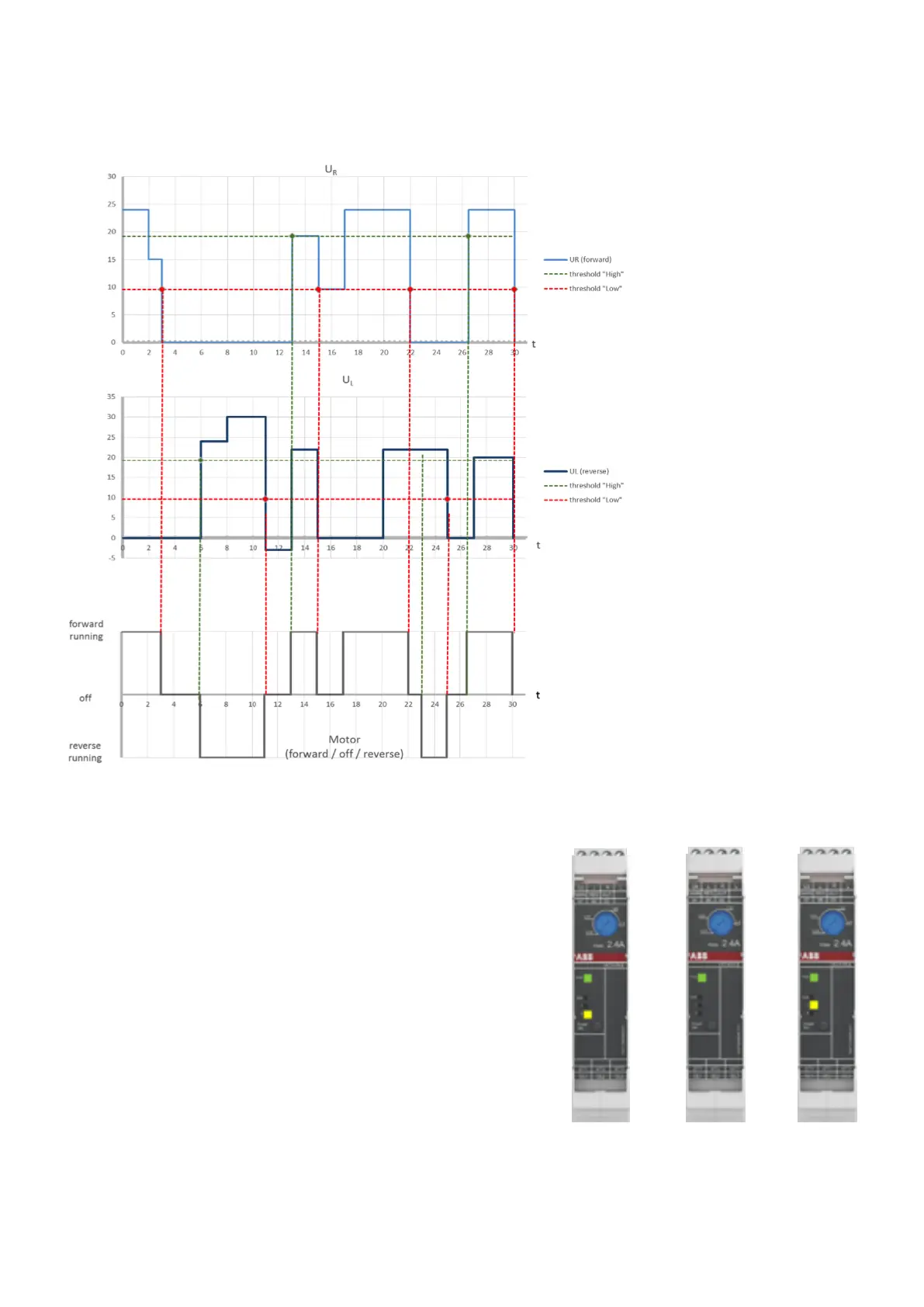
The following figure 12 shows an example voltage characteristic for reversing starters. Please note that this is a simplified
diagram.
—
12 Voltage characteristic of reversing starter
Explanation for diagram 3:
• t
0
: Control voltage applied on U
R
> threshold 'high'
→ motor starts (forward running)
• t
3
: Control voltage applied on U
R
< threshold 'low'
→ motor is switched off
• t
6
: U
L
> threshold 'high' → motor is switched on (reverse running)
• t
11
: U
L
< threshold 'low' → motor is switched off
• t
13
U
R
and U
L
> threshold 'high' → motor is switched on
(forward running)
• t
15
U
R
< threshold 'low' → motor is switched off
• t
17
U
R
> threshold 'high' → motor is switched on (forward running)
• t
22
U
R
< threshold 'low' → motor is switched off
• t
23
: U
L
> threshold 'high' (since t
20
) → motor is switched on
(reverse running) because of automatic restart after short pause
time (< 1 sec.)
• t
25
: U
L
< threshold 'low' → motor is switched off
• t
26
U
R
> threshold 'high' → motor is switched on (forward running)
(because signal U
R
is applied earlier than U
L
)
• t
30
: U
R
< threshold 'low' → motor is switched off
—
t
0
—
t
3
—
t
6
 Loading...