25 ELECTRONIC COMPACT STARTER | MANUAL
LED's on the front side Nominal current [A]
PWR ERR Iadj ON HF0.6-DOL-24VDC
HF2.4-DOLE-24VDC
HF0.6-DOLE-24VDC
HF9-DOL-24VDC
HF2.4-DOL-24VDC
HF9-DOLE-24VDC
L R HF0.6-ROLE-24VDC
HF2.4-ROL-24VDC
HF0.6-ROL-24VDC
HF9-ROLE-24VDC
HF2.4-ROLE-24VDC
HF9-ROL-24VDC
Green Red Yellow
0 0 0 0 0.075 0.18 1.5
0 0 0 1 0.110 0.25 2.0
0 0 1 0 0.145 0.41 2.5
0 0 1 1 0.180 0.56 3.0
0 1 0 0 0.215 0.71 3.5
0 1 0 1 0.250 0.87 4.0
0 1 1 0 0.285 1.02 4.5
0 1 1 1 0.320 1.17 5
1 0 0 0 0.355 1.33 5.5
1 0 0 1 0.390 1.48 6.0
1 0 1 0 0.425 1.63 6.5
1 0 1 1 0.460 1.79 7.0
1 1 0 0 0.495 1.94 7.5
1 1 0 1 0.530 2.09 8.0
1 1 1 0 0.565 2.25 8.5
1 1 1 1 0.600 2.40 9
Table 5 Setting the nominal overload current
Example:
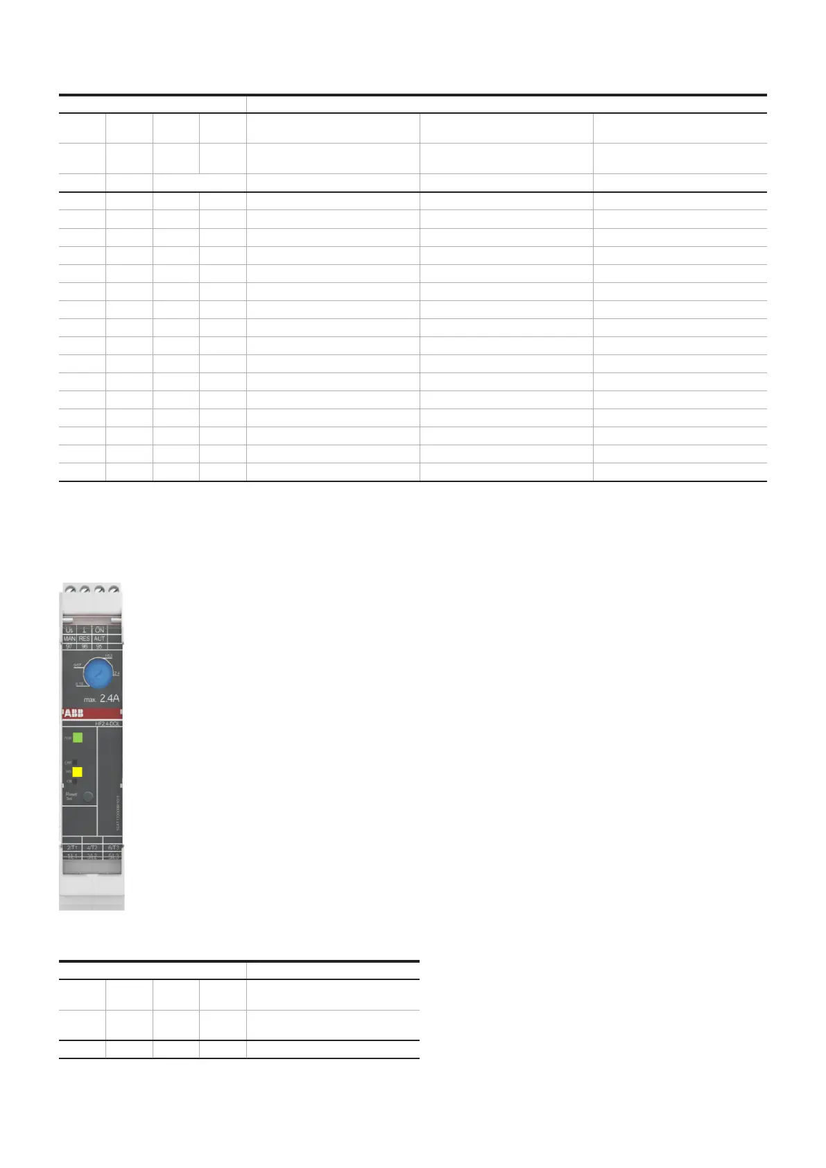
Following figure shows a HF-2.4-DOL-24VDC device with a set nominal current of 1.63 A.
—
17 Example for nominal current setting
LEDs on the front side Nominal current [A]
PWR ERR Iadj ON HF2.4-DOL-24VDC
HF2.4-DOLE-24VDC
L R HF2.4-ROLE-24VDC
HF2.4-ROL-24VDC
1 0 1 0 1.63
Table 6 Illuminated LED at nominal current of 1.63 A
‘PWR’ LED lights in green.
‘ERR’ LED is switched off.
‘Iadj’ / ‘L’ LED lights in yellow.
‘ON’ / ‘R’ LED is switched off.
 Loading...