30 ELECTRONIC COMPACT STARTER | MANUAL
Signaling for DOLE-types
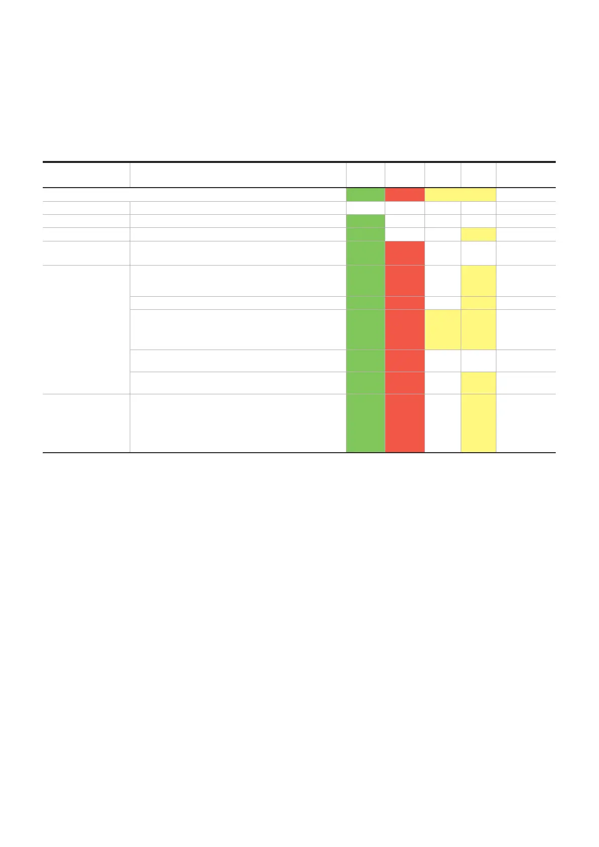
The following table shows the LED codes for
• HF0.6-DOLE-24VDC
• HF2.4-DOLE-24VDC
• HF9-DOLE-24VDC
Operation Status
The electronic compact starter uses the LEDs to indicate the status messages for operation, fault and test:
Status Description PWR ERR I
adj.
ON Error acknow-
ledgment
LED colors on HMI (human machine interface) Green Red Yellow
OFF Supply voltage not present OFF OFF OFF OFF -
Ready to operate Supply voltage present ON OFF OFF OFF -
Drive switched on Forward running motor ON OFF OFF ON
Internal error Internal device error –
device replacement required
ON ON OFF OFF Not possible
External error in the
controller or the I/O
devices (maintenance
requirement, NE44)
Motor protection function: The motor current is higher than
the nominal motor current specification (e.g. Class 10A):
Cooling time is running (20 min.)
ON Flashes OFF ON Automatic
After 2 min., 'ON' flashes: a manual reset is possible ON Flashes OFF Flashes Manual
Error restoring the system state: Checksum error. The
thermal memory of the motor protection function is set to
the maximum value. The error must be manually
acknowledged.
ON Flashes Flashes Flashes Manual
Symmetry: The two motor currents deviate from each other
by more than 33%.
ON Flashes OFF OFF Manual
Blocking: The max. measurable motor current is exceeded
for more than 2 sec..
ON Flashes OFF Flashes Manual
Message (power path
remains switched on)
Message with pending control signal:
- Two or more phases are missing
- No motor connected
- Motor current in at least two phases > 2 sec. minimum
current
value that can be set
Flashes Flashes OFF ON Automatic
Table 11 Signaling DOLE-types
 Loading...