Do you have a question about the ABB InCharge Terra 184 and is the answer not in the manual?
Explains the document's applicability and tasks covered for the EVSE.
Identifies the intended audience for this manual, including owners and engineers.
Details the version, date, and description of manual revisions.
States the original language and translation policy for the document.
Explains the purpose and limitations of illustrations used in the manual.
Specifies the units of measurement used, both SI and North American.
Defines typographical conventions used for lists and step-by-step procedures.
Provides guidance on how to effectively navigate and use the manual.
Explains signal words like Danger, Warning, Caution, and associated symbols.
Details specific symbols used for various risks like voltage, pinching, and hot surfaces.
Lists other relevant documents such as product data sheets and service manuals.
Provides contact information for ABB EV Infrastructure USA and Canada.
Lists common abbreviations used throughout the manual with their definitions.
Defines key terms and concepts used in the EVSE manual.
Defines the orientation conventions for the EVSE unit.
Outlines the manufacturer's liability limitations regarding EVSE usage and modifications.
Provides essential safety guidelines for operating and maintaining the EVSE.
Details the legal responsibilities of the EVSE owner concerning safety and compliance.
Specifies the necessary qualifications and knowledge for installation personnel.
Lists the required personal protective equipment (PPE) for safe EVSE handling.
Provides safety precautions to be followed during the installation process.
Details safety measures to be taken when transporting the EVSE.
Explains the correct procedures and requirements for grounding the EVSE.
Outlines critical safety precautions to observe during the everyday use of the EVSE.
Illustrates and explains various safety symbols found on the EVSE unit.
Provides guidelines for the proper and environmentally sound disposal of the EVSE.
Addresses cyber security considerations for networked EVSEs.
Details the information found on the EVSE's type plate for identification.
Defines the primary purpose and scope of use for the EVSE.
Explains the internal working principles of the EVSE.
Explains the internal working principles for specific Terra x4 CC and CJ variants.
Details the internal working principles for the Terra x4 variant C.
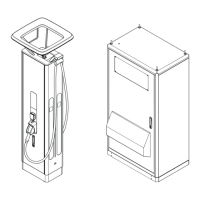
Provides a general overview of the EVSE system and its components.
Provides a general overview of the EVSE system and its components.
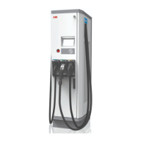
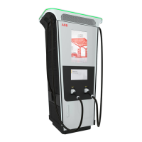
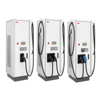
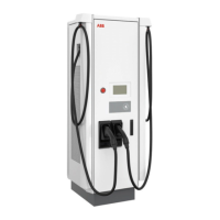
Describes the external features and components of the EVSE unit.
Details the internal components and layout of the EVSE.
Illustrates and explains the cable glands on the charge post.
Shows a visual overview of the EVSE once it has been installed.
Describes the optional cable management system for the EVSE.
Explains the authorization methods for charging sessions.
Describes the functionality of the payment terminal.
Lists and describes available optional features for the EVSE.
Details the EVSE option for CCS 1 connectors on EV charge cables.
Details the EVSE option for CCS 2 connectors on EV charge cables.
Details the EVSE option for CHAdeMO connectors on EV charge cables.
Describes the EVSE option for integrated payment terminals.
Details the optional cable management system for the EVSE.
Explains the function and installation of the optional tilt sensor system.
Describes different strategies for allocating power to charging EVs.
Describes the sequential power allocation strategy where one EV charges at a time.
Details the concurrent power allocation strategy for charging two EVs simultaneously.
Explains the FIFO power allocation strategy for managing multiple charging sessions.
Describes the 'Fair Share' power allocation strategy for balancing charging loads.
Provides guidance on selecting an external residual-current device if required.
Details the touchscreen interface and its functionalities.
Provides a general overview of the touchscreen layout and its elements.
Details the function of various buttons available on the EVSE touchscreen.
Describes the Local Service Portal tool for EVSE configuration and diagnostics.
Introduces ABB's cloud-based tools for EVSE commissioning and monitoring.
Covers the process of transporting the EVSE from the delivery point to its final location.
Details the procedures for unpacking the EVSE.
Details the step-by-step procedure for safely unpacking the EVSE.
Explains how to check transport sensors after unpacking for any damage indicators.
Provides instructions on how to safely remove the EVSE cabinet from its shipping pallet.
Covers procedures for moving the EVSE within the installation site.
Describes the procedure for safely hoisting the EVSE cabinet using lifting equipment.
Explains how to safely move the EVSE cabinet using a forklift truck.
Outlines the overall steps required for installing the EVSE.
Details the necessary steps for preparing the installation site.
Details the necessary steps for preparing the installation site.
Ensures adequate space and airflow around the EVSE cabinet for proper operation.
Details the procedures for preparing the foundation for the EVSE.
Provides general instructions for preparing the foundation for the EVSE.
Details the procedure for preparing a casted concrete foundation.
Explains how to prepare a standard prefabricated foundation for the EVSE.
Covers the process of replacing the standard base with an alternative one.
Details how to safely remove the EVSE unit from its shipping base.
Provides instructions for installing an alternative base with a side entrance.
Explains how to install an alternative base with a reduced height.
Details the steps for the mechanical installation of the EVSE cabinet.
Details the steps for the mechanical installation of the EVSE cabinet.
Details how to open the cable inlet and remove the cable gland.
Explains how to route cables through the cable guide plate.
Covers the process of installing the EVSE cabinet onto the prepared foundation.
Details the procedures for the electrical installation of the EVSE.
Provides the overall procedure for the electrical installation of the EVSE.
Details the procedure for connecting the Protective Earth (PE) wire.
Explains how to properly connect the EVSE enclosure to the earth grounding.
Provides instructions for connecting the AC input wires to the EVSE.
Details the procedure for connecting the Ethernet cable for network communication.
Details the installation of the optional tilt sensor system.
Outlines the general procedure for installing the optional tilt sensors.
Details the steps for installing the mounting bracket for the tilt sensors.
Explains how to install the tilt sensors onto the bracket.
Provides instructions for connecting the tilt sensors to the system.
Details the procedure for installing a ferrule onto a wire.
Explains how to connect a wire that has a ferrule already installed.
Details the installation of the optional cable management system.
Details the preparation steps for the optional cable management system.
Explains how to mount the clamp for the cable management system.
Provides instructions for installing the complete cable management system.
Outlines the necessary preparations before the EVSE commissioning process.
Details the essential steps and checks before operating the EVSE.
Explains how to use the emergency stop button to halt EVSE operation.
Provides instructions on how to reset the EVSE after an emergency stop.
Describes the process of charging an electric vehicle.
Details the procedure for charging an electric vehicle with the EVSE.
Explains how to initiate a new charging session.
Details how to terminate an ongoing charging session.
Covers the procedure for energizing the EVSE to make it ready for operation.
Details the procedures for safely de-energizing the EVSE.
Provides the general steps for safely de-energizing the EVSE.
Details how to measure AC voltage during de-energization.
Explains how to measure DC voltage during de-energization.
Describes the procedure to remove condensation from the EVSE cabinet.
Details operations related to the local service portal.
Explains how to start and access the local service portal application.
Details how to set configuration parameters via the local service portal.
Explains how to configure OCPP parameters using the local service portal.
Provides instructions for installing new software via the local service portal.
Explains how to properly close the local service portal application.
Provides a schedule for routine maintenance tasks for the EVSE.
Details the procedure for cleaning the EVSE cabinet.
Explains how to perform a visual inspection for damage on the EVSE.
Provides instructions for replacing the air inlet filters.
Details the procedure for replacing the air outlet filters.
Explains how to safely open the EVSE doors to access internal components.
Provides instructions for safely closing the EVSE doors.
Details how to remove the border covers from the EVSE.
Explains how to reinstall the border covers onto the EVSE.
Outlines the general procedure for troubleshooting EVSE issues.
A table listing common problems, their possible causes, and solutions.
Describes the coding system for identifying different EVSE types and configurations.
Lists general technical specifications and compliance standards for the EVSE.
Lists the components that are typically included with the EVSE delivery.
Provides technical specifications related to the safe transport of the EVSE.
Lists the necessary tools required for the installation of the EVSE.
Lists the additional parts required for the installation process.
Specifies the correct torque values for various fasteners used during installation.
Details the environmental and operational conditions for the EVSE.
Specifies the maximum noise level emitted by the EVSE.
Details the specifications for the tilt sensor system.
Provides general electrical specifications for the tilt sensor system.
Details the wire specifications for the tilt sensor cables.
Presents the wiring diagram for the tilt sensor installation.
Provides dimensional specifications for the alternative base with reduced height.
Specifies the technical details for the cable management system option.
Provides dimensional data for the EVSE and its components.
Provides general dimensional data for the EVSE cabinet and cable inlet.
Details the dimensions and packaging specifications for the EVSE.
Lists the mass of the EVSE for various models and options.
Provides the center of gravity coordinates for different EVSE models.
Specifies the required floor space around the EVSE for safe operation and access.
Provides dimensions and specifications for a casted foundation.
Details dimensions and requirements for prefabricated foundations.
Provides dimensional specifications for the alternative base with side entrance.
Specifies the required cable slack for Ethernet and AC input cables.
Details heights of user operable elements according to ADA standards.
Details specifications for communication interfaces.
Covers general specifications for RFID and network connectivity.
Provides specifications for the Ethernet cable, including type and bandwidth.
Details the power ratings of the EVSE for different operational modes.
Lists EVSE power ratings for normal duty operation across different models.
Shows how EVSE power output derates based on ambient temperature.
Lists EVSE power ratings for heavy duty operation across different models.
Shows how EVSE power output derates in heavy duty operation based on temperature.
Presents harmonic data for the EVSE's impact on the grid.
Presents harmonic data for the Terra 184 model.
Presents harmonic data for Terra 124 and 104 models.
Presents harmonic data for the Terra 94 model.
Details specifications for the AC input power.
Details AC input specifications like voltage, power factor, and efficiency.
Provides specifications for AC input wires, including material and diameter.
Specifies AC input parameters for the Terra 94 model.
Specifies AC input parameters for the Terra 104 model.
Specifies AC input parameters for the Terra 124 model.
Specifies AC input parameters for the Terra 184 model.
Details specifications for the DC output power.
Details general DC output specifications, including voltage range and connection standards.
Presents DC output specifications for the Terra 94 model.
Presents DC output specifications for the Terra 104 model.
Presents DC output specifications for the Terra 124 model.
Presents DC output specifications for the Terra 184 model.
Details the power consumption of the EVSE during stand-by.
Specifies in-rush current characteristics during charge session start.
Provides a maintenance schedule for service engineers over several years.
Specifies cleaning agents and tools for EVSE maintenance.
Lists spare parts for the EVSE and their quantities.
Contains the official declaration of conformity for the EVSE product.
| Type | DC Fast Charger |
|---|---|
| Product Type | EV Charger |
| Input Voltage | 400 V AC |
| Operating Temperature | -30°C to +50°C |
| Protection Class | IP54 |
| Input Current | 32 A |
| Number of Outlets | 1 |
| Output Current | 32 A |
| Efficiency | > 95% |
| Charging Standards | CCS, CHAdeMO |
| Communication Interface | Ethernet, 4G |