Do you have a question about the ABB Terra HP Generation 4 CE Ionity and is the answer not in the manual?
Explains the applicability of the EVSE document.
Identifies intended users for the installation manual.
Lists document versions and their release dates.
Specifies the original and translated language versions.
Clarifies the purpose and nature of illustrations used.
States the measurement system used in the document.
Explains formatting and numbering used in procedures.
Provides guidance on reading and applying the manual.
Explains symbols and signal words for warnings and information.
Details specific symbols for risks like voltage and heat.
Lists other relevant documentation for the EVSE.
Provides manufacturer details and contact information.
Lists abbreviations used in the document with their definitions.
Defines key terms used in the installation manual.
Defines orientation axes (X, Y, Z) for EVSE components.
Manufacturer's liability disclaimer and conditions.
General safety rules and compliance requirements.
Specifies necessary skills and qualifications for installers.
Lists required PPE for safe handling and installation.
Outlines safety measures for transporting the EVSE.
Provides safety guidelines for the installation process.
Details procedures for proper earthing connection.
Explains warning and information signs found on the EVSE.
Provides guidance on safe and compliant disposal of the EVSE.
Discusses security measures for connected EVSE systems.
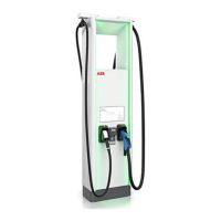
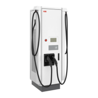
Defines the purpose and operational scope of the EVSE.
Explains the information presented on the EVSE's identification plate.
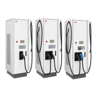
Overview of the EVSE's main components and arrangement.
Illustrates the functional flow and interconnections of the EVSE.
Details the functions and components of the EVSE.
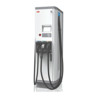
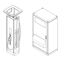
Details the external features and components of the power cabinet.
Describes the internal components and layout of the power cabinet.
Details the AC connection terminals and layout within the power cabinet.
Details the DC connection terminals and layout within the power cabinet.
Shows the location and purpose of cable entry points in the power cabinet.
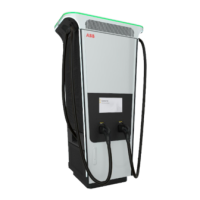
Illustrates the external features of the charge post.
Details the internal components and layout of the charge post.
Identifies and explains the cable glands on the charge post.
Explains the function of the EVSS for site load management.
Describes the tilt sensor supply for safety and emergency functions.
Describes the standard CCS 2 EV charging cable.
Explains the function of the parking sensor for object detection.
Outlines methods for authorizing EV charging sessions.
Explains the user interface for payment processing.
Details the optional MID compliant DC energy meter for billing.
Outlines the initial steps for site preparation and planning.
Details site preparation requirements for EVSE installation.
Emphasizes correct space and airflow for EVSE operation.
Provides general guidelines for foundation preparation.
Details preparation for a prefabricated concrete foundation.
Outlines steps for preparing a metal foundation for the power cabinet.
Guides on preparing a prefabricated concrete foundation for the charge post.
Details preparation for a metal foundation for the charge post.
Explains how to prepare a custom foundation for the charge post.
Instructions for installing a grommet plate on a concrete foundation.
Details responsibilities for transporting the EVSE to the installation site.
Steps for checking the EVSE upon arrival.
How to verify transport sensors for shocks and tilt.
Guidance on removing packaging materials from the EVSE.
Instructions for safely removing the power cabinet from its pallet.
General guidelines for moving the EVSE within the site.
Procedure for orienting the charge post vertically for installation.
How to move the power cabinet using a forklift.
Instructions for lifting the power cabinet using hoisting equipment.
Overview of the overall installation process and requirements.
Steps for mechanically installing the power cabinet.
General steps for mechanically installing the power cabinet.
Steps to secure the cabinet onto its prepared foundation.
Procedure for installing cover plates for metal foundations.
Steps for mechanically installing the charge post.
General steps for mechanically installing the charge post.
Instructions for removing cable gland plates from the charge post.
Steps to mount the charge post onto its foundation.
Procedure for installing cable gland plates on the charge post.
Overview of the electrical installation steps for the power cabinet.
Detailed steps for connecting the protective earth (PE) cable.
Instructions for connecting AC power cables to the power cabinet.
Steps for connecting DC power cables within the power cabinet.
Guidance on connecting the AC auxiliary power cable.
How to connect interlock and DC guard cables to the power cabinet.
Instructions for connecting the Ethernet cable to the power cabinet.
Overview of electrical installation steps for the charge post.
Detailed steps for connecting the protective earth (PE) cable to the charge post.
Steps for connecting DC power input cables to the charge post.
Guidance on connecting the AC auxiliary power cable to the charge post.
How to connect interlock and DC guard cables to the charge post.
Instructions for connecting the Ethernet cable to the power cabinet.
Steps to set the charger to pre-commissioning mode.
Steps to open the power cabinet door safely.
Instructions for removing the plinth covers from the power cabinet.
Steps to open the DC door on the power cabinet.
Procedure for removing the AC cover from the power cabinet.
Instructions for securely closing and locking the power cabinet door.
Steps to open the charge post door safely.
Instructions for removing plinth covers from the charge post.
Procedure for removing the protection plate from the charge post.
Steps for installing the AC cover onto the power cabinet.
Instructions for securely closing and locking the DC door.
Steps for securely closing and locking the charge post door.
Step-by-step guide to installing a cable lug on electrical wire.
Procedure for installing a ferrule onto electrical wire.
How to apply insulating heatshrink tubing to wires.
Steps to connect a wire with an installed cable lug to a terminal.
Procedure for connecting a wire with a ferrule to a terminal.
Explains the coding system for EVSE model identification.
Lists components included in the EVSE delivery package.
Lists all tools necessary for installing the EVSE.
Lists all parts required for the EVSE installation.
Provides general specifications like compliance and ingress protection.
Specifies general electrical installation requirements.
Specifies general electrical installation requirements.
Lists requirements before the EVSE can be commissioned.
Details specific requirements for the charge post auxiliary.
Provides technical specifications for the DC output.
Details current peak characteristics during DC charging start.
Specifies technical details for logic interfaces.
Provides information on mass and center of gravity.
Provides the mass of the power cabinet and charge post.
Details the center of gravity for the power cabinet.
Details the center of gravity for the charge post.
Specifies operating and storage ambient conditions.
Provides noise level specifications for the EVSE components.
Lists torque values for various fasteners and connections.
Provides dimensional data for EVSE components.
Provides dimensional data for the power cabinet.
Provides dimensional data for the charge post.
Details the height of user interface elements on the charge post.
Specifies space requirements for EVSE placement.
Specifies space requirements for power cabinet configurations.
Specifies space requirements for charge post placement.
Guidelines for obstacles around the charge post for maintenance.
Specifies minimum distances between cabinets and posts.
Provides specifications for various foundation types.
Details specifications for prefabricated concrete foundations for cabinets.
Specifies requirements for metal frame foundations for power cabinets.
Details gland plates for metal foundations of power cabinets.
Specifies requirements for metal frame foundations for charge posts.
Details specifications for prefabricated concrete foundations for charge posts.
Details gland plates for metal foundations of charge posts.
Specifies requirements for custom foundations for charge posts.
Provides an overview of cable conduit routing and connections.
Details specifications for various cables used in the EVSE.
Details specifications for the AC input cable to the power cabinet.
Specifies technical details for DC power cables.
Details specifications for the PE (protective earth) cable.
Details specifications for AC auxiliary power cables.
Specifies technical details for interlock and DC guard cables.
Details specifications for the Ethernet cable.
Provides a visual representation of the EVSE's electrical connections.
Shows expected wye input configurations for Canada and USA.
| Output Current | up to 500 A |
|---|---|
| Input Frequency | 50/60 Hz |
| Number of Outlets | 2 |
| Enclosure Rating | IP54 |
| Operating Temperature | -30°C to +50°C |
| Cooling System | Liquid Cooling |
| User Interface | Touchscreen |
| Efficiency | > 95% |
| Protection Class | Class I |
| Communication | OCPP 1.6 |
| Charging Standards | CCS |
| Input Voltage | 400 V |
| Connectivity | Ethernet |
| Weight | 800 kg |
| Type | High Power DC Charger |