Chapter 2
MicrOS 410 Installation Guide 24
Connecting the Serial Cable
1. Have the Ethernet data cable, nut, rubber boots, and cable gland available.
2. Remove the cable gland from the bottom of the MicrOS 410. For power and Ethernet
connectivity, use Port 1.
3. Press the tab on the RJ45 connector down as you push the cable through the nut. Make sure
that the orientation is consistent with
Figure 5.
4. Separate the rubber boot as needed and slide the connector through the boot. Use the boot
with the smaller diameter opening, unless the cable is too wide to permit the boot to close
completely. Use only one boot.
5. Slide the cable through the cable gland.
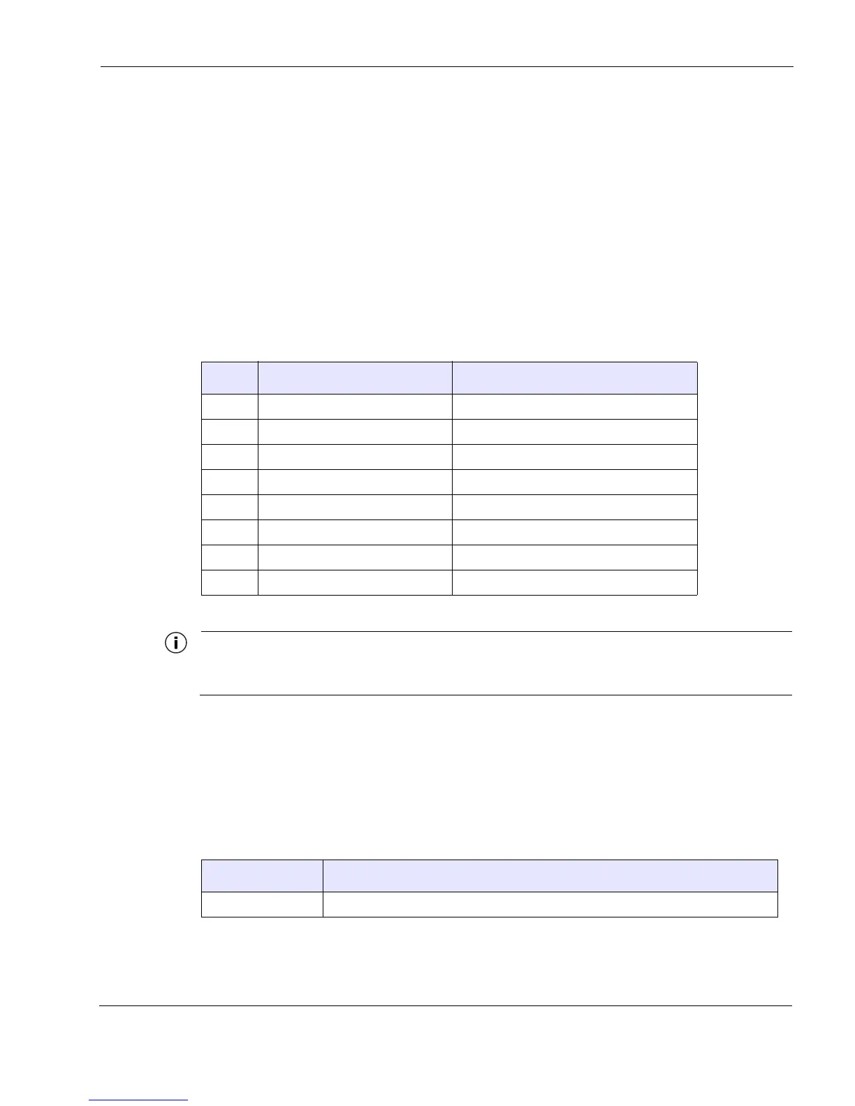
When using one RS-232 port, as shown in Option 1 in Table 7 (pin 1=TX, pin 3=RX), the Configuration
Utility for the serial port should be set up for port 2 (for more information, see the MicrOS 410 User Guide).
LED Status Indicator
The MicrOS 410 is equipped with LED status indicator. The LED indicator has three states, as
shown in
Table 8.
Table 7 Serial Pin Assignments
Pin Option 1 (one serial port) Option 2 (two serial ports)
1 RS232 TX or RS485 TXRX - RS232 (port 2) TX or RS485 TXRX -
2GND GND
3 RS232 RX or RS485 TXRX + RS232 (port 2) RX or RS485 TXRX +
4 not used not used
5 not used RS232 (port 1) RX
6 not used RS232 (port 1) TX
7 not used not used
8 not used not used
Table 8 LED Indicator States
State
Description
Off The unit has no power or is not operating.