________________________________________________________________________________________________________
AC500-eCo - 8 -
Hardware Introduction
2. AC500-eCo Hardware Descriptions
2.1 CPU Overview
The CPU PM554 and PM564 is the central unit of the AC500 system with the onboard
digital/analog inputs and outputs. The CPUs can be powered by 24V DC or 100-240V AC
depending on different variant.
The different between two CPU types is the onboard I/O type.
Each AC500 CPU PM554 and PM564 can be used as
Bus Master within the control System AC500 together with CS31 or/and Modbus;
Stand-alone CPU.
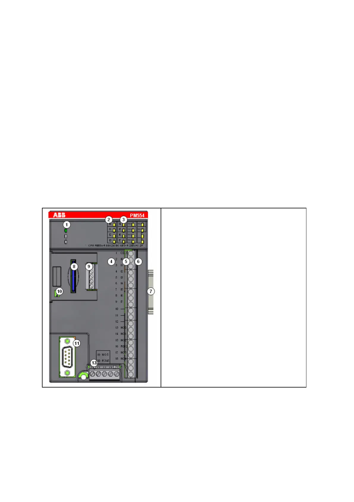
2.1.1 CPU components
Take CPU PM554 as the example:
1. 3 LEDs to display the CPU statuses
2. Allocation of signal name (with 4 and 5
correspondences)
3. yellow LEDs to display the inputs and the output
(8 IN and 6 OUT)
4. Allocation of terminal number
5. Allocation of signal name
6. 9 and 11 poles I/O terminal block( fixed
screw-type terminals)
7. DIN rail
8. SD Card (Option)
9. COM2 + RTC (Option)
10. RUN/STOP switch
11. COM1 RS485
12. Power supply terminal