________________________________________________________________________________________________________
AC500-eCo - 9 -
Hardware Introduction
2.1.2 CPU Assortments
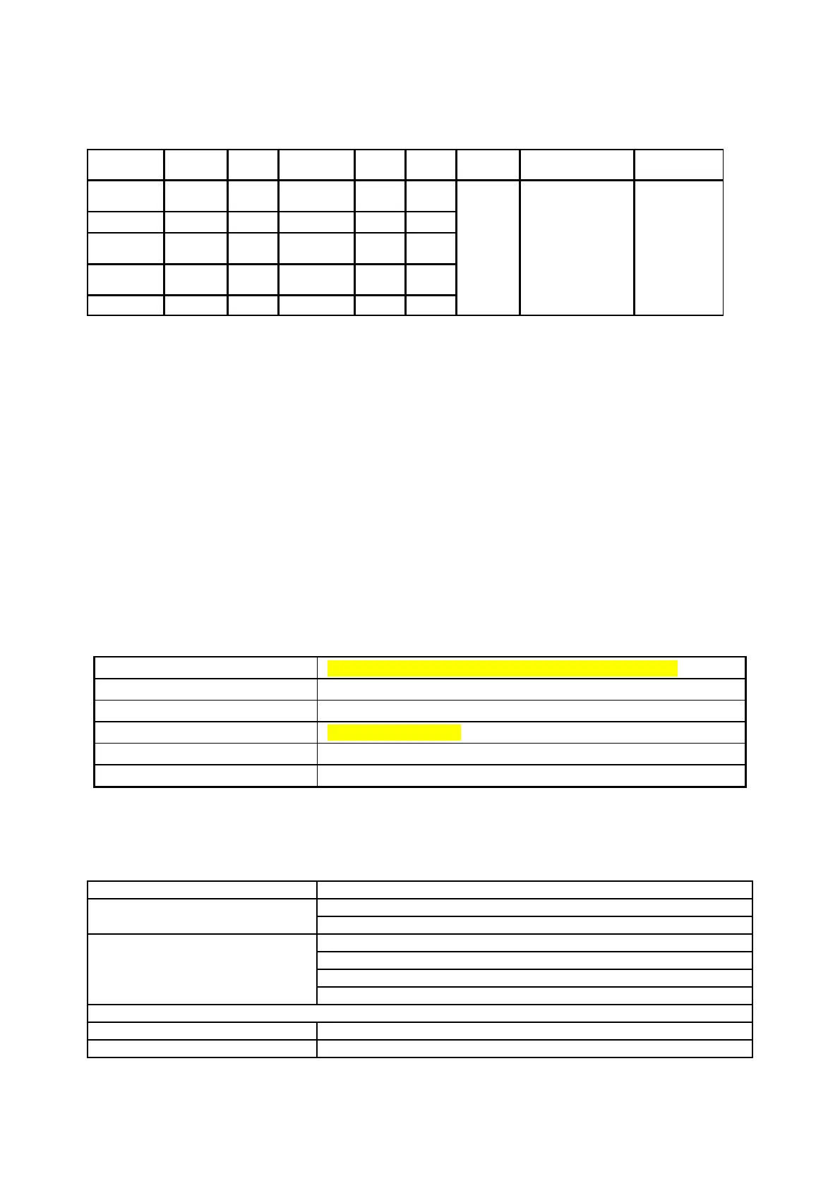
AC500 CPUs PM554 and PM564 have the following five Assortments:
CPU types
Power
Supply
Digital
Inputs
Digital
Outputs
Analog
Inputs*
Analog
Output
Program
Memory
instructions
Other
Interface
PM554-T
24V DC 8 x 6 x
Transistor
- -
PM554-R
24V DC 8 x 6 x Relay - -
PM554-R
100 ~
240V AC
8 x 6 x Relay - -
PM564-T
24V DC 6 x 6 x
Transistor
2 1
PM564-R
24V DC 6 x 6 x Relay 2 1
128kB
Binary:
0.3 ms
Word:
0.3 ms
Floating point:
6ms
Serial
interfaces
COM1 and
I/O-Bus,
interface to SD
card (option)
* can be configured as digital inputs or analog inputs
2.1.3 The CPU onboard I/Os
New onboard I/O Function has been added on the AC500 CPU PM554 and PM564.
The AC500 CPU onboard digital channels are equipped with a filter function to prevent incorrect
operation caused by chatter or noise in the input signal. The user can select an input time
constant of 0.1ms, 1ms, 8 ms or 32 ms; it’s have two configurable PWM (channel 2, 3) outputs.
The AC500 CPU PM564 has 2 configurable analog inputs and 1 analog output: The analog input
range can be set to 0 to 10 VDC; the analog output range can be set to 0 to 10 VDC, 0 to 20mA,
or 4 to 20mA.
CPU PM554
The AC500 CPU PM554 has following functionality:
Digital inputs
8 (±24 V DC) , transistor or relay, sink or source (I0…I7)
Interrupt inputs
4 (I0…I3), configurable
High-speed counter
1 (I0), configurable
Digital outputs
6 (+24 V DC), source
PWM outputs
2, configurable
LED displays
For signal status
CPU PM564
The AC500 CPU PM564 has following functionality:
6 DI + 6 DO
Same as PM554
Unused (default setting)
2 analog Inputs,
Individually configurable for
0 … 10V or digital inputs
Unused (default setting)
0 … 10V
0 … 20mA
1 analog outputs,
Individually configurable for
4 … 20mA
Resolution of the analog channels
- Voltage 0 … 10V 10 bits
- Current 0 … 20mA, 4 … 20mA 10 bits