24 PositionMaster EDP300 DIGITAL POSITIONER | OI/EDP300-EN REV. D
… 7 Installation
… Electrical connections
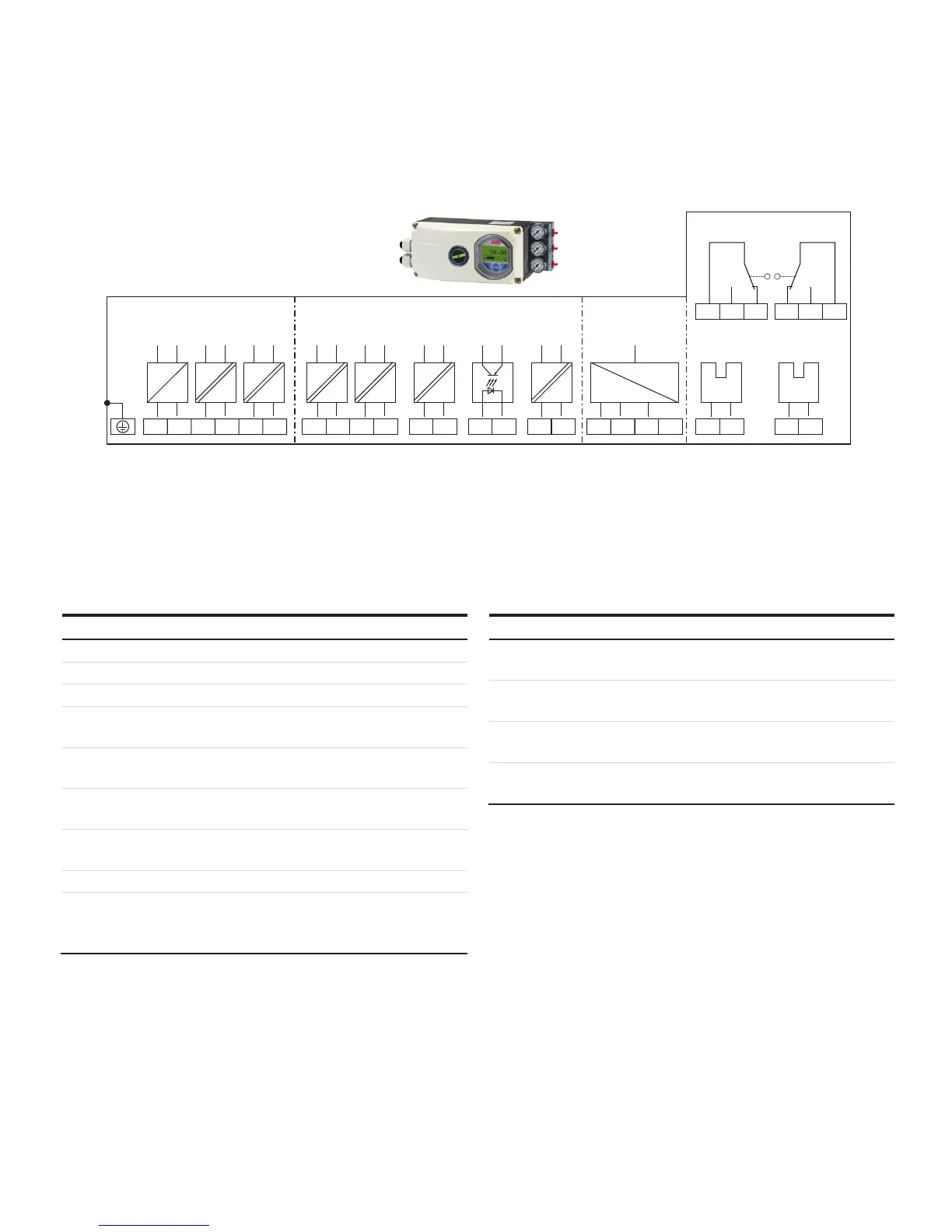
Positioner / EDP300 Control Unit Electrical Connection
M
+11
-12
+81
-82
+83 -84
DI DOAI
+51 -52
SW2
+41 -42
SW1
+31 -32
AO
+85 -86 123
A
D
AB
UAI
-22+21
+51 -52 +41 -42
41
42
43
51
52
53
D
Limit 1 Limit 2
Limit 1 Limit 2
C
A Basic device
B Options
C Connection EDP Remote Sensor / remote position sensor
(only for EDP Control Unit version)
D Options, limit monitor with proximity switches or microswitches
(not for EDP300 Control Unit)
Figure 20: EDP300 Electrical Connection
Change from one to tw o columns
Connections for inputs and outputs
Terminal Function / comments
+11 / Æ12
Analog input AI or field bus connection
+81 / Æ82
Digital input DI
+83 / Æ84
Digital output DO2
+51 / Æ52
Limit alarm SW1
(Option module)
+41 / Æ42
Limit alarm SW2
(Option module)
+31 / Æ32
Analog feedback AO
(Option module)
+85 / Æ86
Emergency shutdown module
(Option module)
+21 / Æ22
Universal input UAI
1 / 2 / 3
EDP300 remote sensor
(Only for options EDP300 Remote Sensor or EDP300 for
remote position sensor)
Terminal Function / comments
+51 / Æ52
Limit switch Limit 1 with proximity switch
(optional)
+41 / Æ42
Limit switch Limit 2 with proximity switch
(optional)
51 / 52 / 53
Limit switch Limit 1 with microswitch
(optional)
41 / 42 / 43
Limit switch Limit 2 with microswitch
(optional)
Change from two to one column