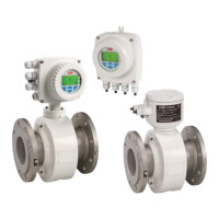
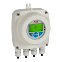
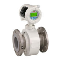
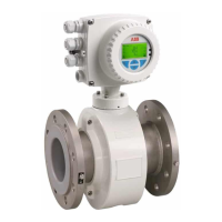
Do you have a question about the ABB ProcessMaster FEP612 and is the answer not in the manual?
Important part of the product, must be retained. Only trained personnel authorized by plant operator can install, commission, and maintain.
Defines signal words DANGER, WARNING, CAUTION, and NOTE to indicate hazards and important information.
For transmitting fluid, pulpy or pasty media with electrical conductivity for volume and mass flow measurement.
General information on installation, including flow direction, torque, mechanical tension, gasket compatibility, and temperature limits.
Details on installing the sensor, including removing protective plates, positioning, gasket usage, and tightening sequence.
General information and specific methods for grounding the flowmeter sensor in various pipeline types and configurations.
Observing power supply limit values, voltage drop, and connecting L, N, PE terminals as per name plate.
Detailed electrical specifications for power supply, current output, and digital outputs (pulse, frequency, binary).
Cautions regarding hot measuring media, aggressive/abrasive media, and pressurized media escape from worn seals.
Describes the write-protection switch, service LED functions, and the local operating interface for parameterization.
Checks before commissioning: wiring completion, sensor grounding, ambient conditions, and power supply requirements.
Options for device parameterization via integrated LCD indicator, optional display, or ABB AssetVision software.
Guides through the 'Easy Setup' menu for fast configuration of common parameters like language, units, and ranges.
Cautions regarding hot media, aggressive media, and potential pressurized media escape from worn seals.
Explains how to navigate the LCD display using capacitive buttons and details the function of each button.
Explains how error messages appear, their grouping by NAMUR classification, and division by areas (Operation, Sensor, Electronics, Configuration).
Details how to switch to the configuration level, select access level (Read Only, Standard, Advanced), and password definition.
Guides on selecting values from tables or performing numerical/alphanumeric entries for parameters.
Detailed descriptions of parameters categorized by menus like Easy Setup, Device Info, Device Setup, Display, Input/Output, Process Alarm, Diagnostics, Totalizer.
Description of parameters available in the 'Easy Setup' menu, covering language, units, range, pulses, damping, and alarms.
Details device setup parameters such as access control, sensor configuration (ranges, tags), and transmitter settings.
Configuration of current and digital outputs, including output value, mode, alarm status, and pulse/frequency settings.
Management of process alarms, including history, group masking, and setting alarm limits for mass and volume flow.
Tools for diagnosing device status, including maintenance control, diagnosis control (empty pipe, noise), fingerprints, and internal values.
Procedure to access error details from the process display via the operator menu and diagnostics submenu.
Categorizes errors by range (Electronics, Config, Operation) and provides text, cause, and remedy.
Lists specific electronic errors with their LCD display text, cause, and recommended remedy.
Details operation errors related to ambient temperature, EPD alarm, sensor temperature limits, saturation, and pulse output.
Safety precautions for maintenance, including risk of injury from live parts, hot media, and electronic component damage.
Steps for replacing the flowmeter sensor, including power supply, signal cable disconnection, and system data replication.
Provides permissible medium temperature and pressure limits based on liner material for ProcessMaster Design Level A and B sensors.
Shows permissible pressure and temperature limits for HygienicMaster based on process connection, DN, and liner material.
Provides torque specifications for flange and wafer-type designs based on nominal diameter, pressure rating, and material.
| Type | Electromagnetic Flowmeter |
|---|---|
| Measurement Principle | Electromagnetic induction |
| Process Connection | Flange |
| Lining Material | PTFE, PFA, Rubber |
| Electrode Material | Stainless Steel, Hastelloy, Titanium |
| Fluid Temperature | -20°C to +180°C (depending on lining material) |
| Process Pressure | Up to 40 bar |
| Output Signal | 4-20 mA, Pulse |
| Power Supply | 24 V DC |
| Protection Class | IP67 |
| Material | Stainless steel |
| Communication Protocols | HART, PROFIBUS PA |
| Certifications | ATEX, FM |


