1SFC132374M0201 6
2.3 Connection Setup
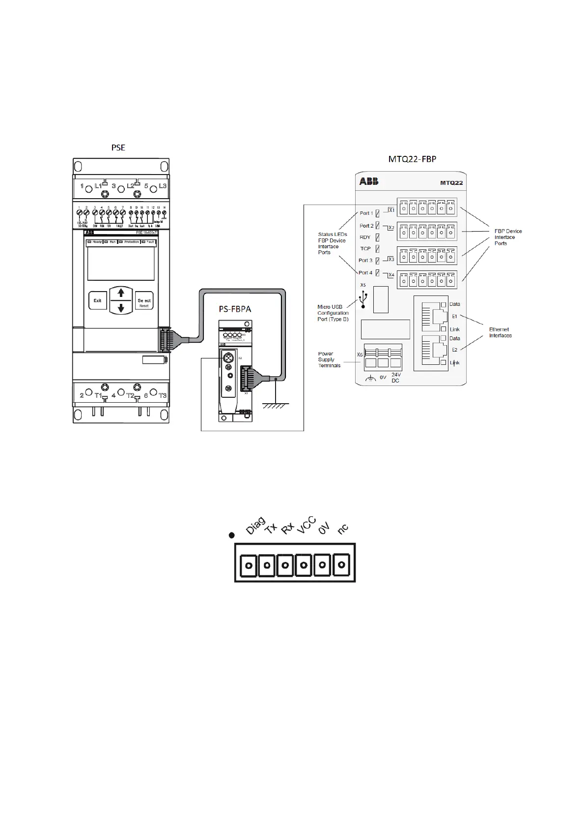
In order for Modbus to function properly the PSE must be connected point-to-point with a Fieldbus Plug
Accessory (PS-FBPA) as seen in Figure 2. Further the PS-FBPA must be connected to one of the ports named
X1 to X4 on the MTQ22-FBP. The Modbus master is in turn connected to one of the Ethernet connections E1 or
E2.
Figure 2: Device connections required to enable a Modbus TCP connection between the PSE and a Modbus master.
The cable connecting the PS-FBPA and the MTQ22-FBP, a CDP19-FBP .100 cable must be purchased
separately. A spring terminal block connector must also be installed on the separate cable and connected
according to Figure 3.
Figure 3: MTQ22-FBP port connection specification.