40 Connection | Installation and commissioning manual | 1SFC132081M0201
5.1.2 Control supply and control circuit
Wires in industrial control applications are divided into 3
groups: main power supply, control supply and control
circuit.
Main power supply (1L1, 3L2, 5L3, 2T1, 4T2, 6T3)
Control supply voltage (terminals 1 and 2)
Control circuit (terminals 13 - 21).
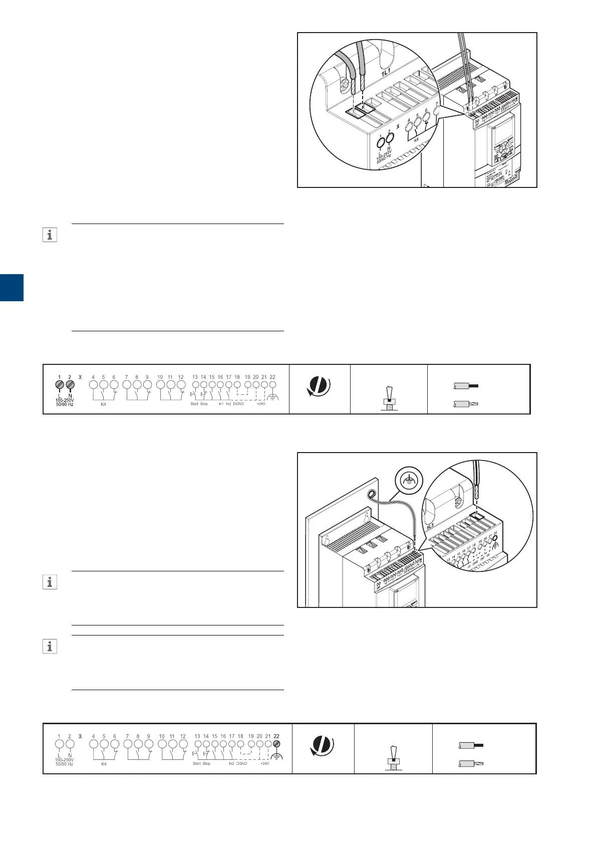
5.1.2.1 Control supply voltage -
terminals1and2
Connect neutral and phase to terminal 1 and 2.
See Figure 5.4.
INFORMATION
Make sure that you have the correct supply
voltage U
s
. See chapter 3.2.1 General.
The control supply voltage for all PSTX
Softstarters is Us 100-250V AC,50/60Hz.
If using the operational voltage (Phase /N) as
source for control voltage make sure to not
exceed Us 250V –AC,50/60Hz
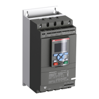
Tightening torques and cable dimensions.
0,2 .. 2,5 mm
2
2x0,2 .. 1,5 mm
2
0,2 .. 2,5 mm
2
2x0,2 .. 1,5 mm
2
AWG 12 ... 24
0,5 Nm
4,3 lb.in
3,5 x 0,6 mm
(0.138 x 0.024 in)
M3,5
L
100-250V
50/60 Hz K4 K5 K6
Start Stop In0 In1 In2 GND +24V
N
1SFC132081M0201
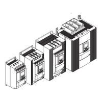
5.1.2.2 Functional ground - terminal 22
Ground the Softstarters with the terminals as shown in
Figure 5.5 (one connection is sufficient). Connect the
cable to a ground point close to the Softstarter. A suitable
ground point is next to the Softstarter on the installation
plate. Ground the installation plate.
INFORMATION
This is not a protective ground, it is a function
ground. The grounding cable must be as short as
possible. Maximum length 0,5m.
INFORMATION
Do not use functional ground in IT-networks,
commonly found in for instance marine
applications.
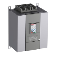
Tightening torques and cable dimensions.
0,2 .. 2,5 mm
2
2x0,2 .. 1,5 mm
2
0,2 .. 2,5 mm
2
2x0,2 .. 1,5 mm
2
AWG 12 ... 24
0,5 Nm
4,3 lb.in
3,5 x 0,6 mm
(0.138 x 0.024 in)
M3
L
100-250V
50/60 Hz K4 K5 K6
Start Stop In0 In1 In2 DGND GND +24V
N
1SFC132081M0201
Figure 5.4
Supply voltage and control circuit
1SFC132081M0201
Figure 5.5
Functional ground, terminal 22
1SFC132081M0201
5