Motor Protection Relay REM 610
1MRS 755121
Connection diagrams
(cont´d)
11
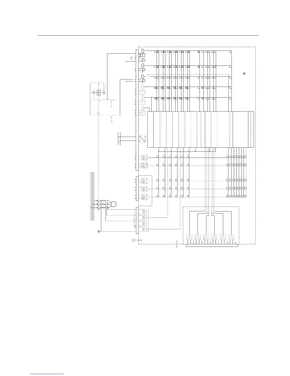
Fig. 3 Residual current is measured via a summation connection of the phase current transformers.
X3.1
6 5 4 3 2 1
X4.1
RTD1/Th1
RTD2
RTD3
RTD4/Th2
RTD5
RTD6
1
1
1 1
1
2
2 2 2 2
3
3 3 3 3
4
4 4 4 4
5
5 5 5 5
6
6
6 6
6
7
7 7 7 7
8
8 8 8 8
9
9 9 9 9
10
10
10
10 10
11
11 11 11 11
12
12
12 12 12
13
13 13 13 13
14 14
14 14 14
16 16 16
16 16
17 17
17 17 17
18
18
18
18 18
19 19
19
19
19
15
15
15
15
15
SGF1/7
SGR4
SGR3
SGR2 SGR1
SGR5
SO1
PO2
SO2
3 4 5 6 7 8 9 10 11 12 13 14 15 16 17 18 19
X2.1
7 8 1 2 3 4 5 6
0
1
O
I
-
-
+
PO3
+
21 22 23 24
1 2
~
U
aux
M
3 ~
DIFF
+
-
7
8
9
10
11
12
13
14
15
16
17
18
19
20
21
22
23
24
X3.1
θ>
I
s
2
t
s
/I
s
>
I>>
I<
I
0
>
I
2
>
REV
ThA>
ThB>
Σt
si
SGF1...SGF5
SGL1...SGL8
DIFF
+
-
DIFF
+
-
DIFF
+
-
DIFF
+
-
DIFF
+
-
L1
L2
L3
ConnDiagr2REM610_b
PO1
+
COMMON
COMMON
COMMON
COMMON
COMMON
COMMON
1
1 1 1 1
2
2
2 2
2
3
3
3 3
3
4
4
4 4
4
6
6
6 6
6
7
7
7 7
7
8
8
8 8
8
9
9
9 9
9
10
10
10 10
10
11
11
11 11
11
12
12
12 12
12
13
13
13 13
13
14
14
14 14
14
SGB4
SGB3
SGB2
SGB1
SGB5
5
5
5 5
5
~
DI3
DI2
DI1
DI4
DI5
Optional
= Factory default
* Restart inhibit
ALA R M
TRIP
START
TRIP
Speed switch/blocking
START
TRIP
Blocking
START
TRIP
Blocking
START
TRIP
Blocking
START
TRIP
Blocking
TRIP
Motor start up
MOTOR ST
ALARM
TRIP
Emergency start
ALARM
TRIP
Emergency start
** Restart inhibit
Restart inhibit
RESTART INHIBIT
* Restart inhibit signal from θ>
** Restart inhibit signal from Σt
s
i
TRIP
External restart inhibit
External triggering of CBFP
Indications cleared
Output contacts unlatched
Memorized values cleared
Setting group selection
Time sync
EXT TRIP
External trip
Emergency start
Emergency start
Optional
Self-supervision
IRF
IRF
Warning

 Loading...


