Motor Protection Relay REM 610
1MRS 755121
Technical data (cont´d)
7
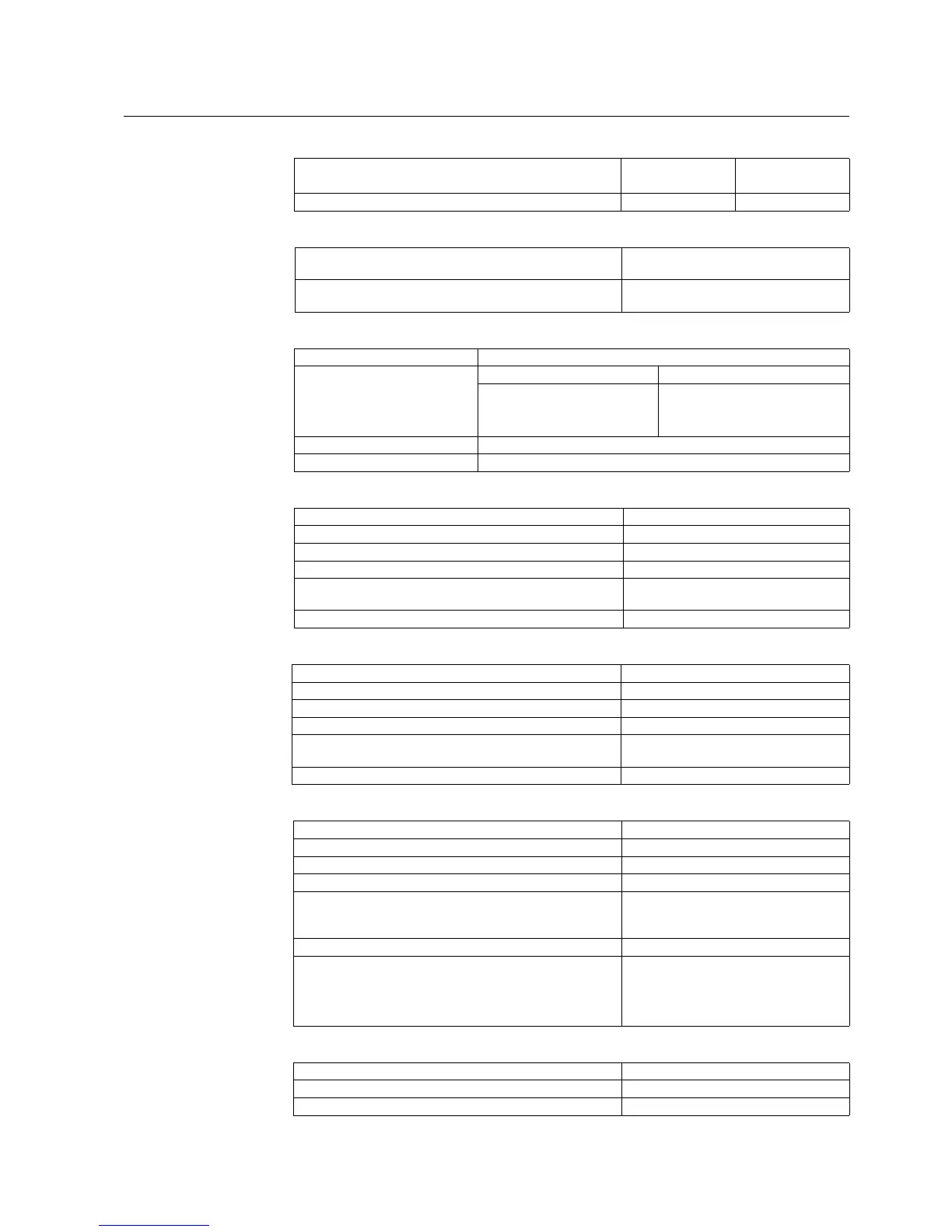
Dynamic current withstand
half-wave value 250 A 1250 A
Input impedance <100 mΩ <20 mΩ
Table 5: Measuring range
Measured currents on phases I
L1
, I
L2
and I
L3
as multiples of
the rated currents of the energizing inputs
0...50 x I
n
Earth-fault current as a multiple of the rated current of the
energizing input
0...8 x I
n
Table 6: Digital inputs
Operating range ±20% of the rated voltage
Rated voltage: DI1...DI2 DI3...DI5 (optional)
• REM610BxxHxxx 110/125/220/250 V dc
• REM610BxxLxxx 24/48/60/110/125/220/250 V dc
• REM610BxxxxMx 24/48/60/110/125/220/250 V dc
Current drain 2...18 mA
Power consumption/input <0.9 W
Table 7: Signal outputs SO1
Rated voltage 250 V ac/dc
Continuous carry 5 A
Make and carry for 3.0 s 15 A
Make and carry for 0.5 s 30 A
Breaking capacity when the control-circuit time constant L/R
<40 ms, at 48/110/220 V dc
1 A/0.25 A/0.15 A
Minimum contact load 100 mA at 24 V ac/dc
Table 8: Signal outputs SO2 and self-supervision (IRF) output
Rated voltage 250 V ac/dc
Continuous carry 5 A
Make and carry for 3.0 s 10 A
Make and carry for 0.5 s 15 A
Breaking capacity when the control-circuit time constant L/R
<40 ms, at 48/110/220 V dc
1 A/0.25 A/0.15 A
Minimum contact load 100 mA at 24 V ac/dc
Table 9: Power outputs (PO1, PO2, PO3)
Rated voltage 250 V ac/dc
Continuous carry 5 A
Make and carry for 3.0 s 15 A
Make and carry for 0.5 s 30 A
Breaking capacity when the control-circuit time constant L/R
<40 ms, at 48/110/220 V dc (PO1 with both contacts
connected in series)
5 A/3 A/1 A
Minimum contact load 100 mA at 24 V ac/dc
TCS
Control voltage range 20...265 V ac/dc
Current drain through the supervision circuit ~1.5 mA
Minimum voltage over a contact 20 V ac/dc (15...20 V)
Table 10: Enclosure class of the flush-mounted relay
Front side IP 54
Rear side, top of the relay IP 40
Rear side, connection terminals IP 20
Table 4: Energizing inputs

 Loading...


