Arc Protection Relay REA 10_
1MRS750929-MBG
4
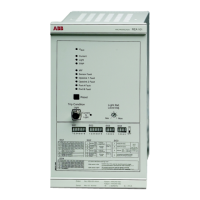
Design Arc protection relay REA 101
Overcurrent detection unit
The selection switch is used to select between
three-phase current measurement or two-
phase and neutral current measurement.
Three-phase current measurement
The three-phase currents are measured via
transformers. When the current on one phase
exceeds the selected reference level, an over-
current signal is activated.
The selection switch is us
ed to select the cur-
rent reference level for the
current inputs L1,
L2 and L3. The available current level set-
tings are 0.5, 1.0, 1.5, 2.5,
3.0, 5.0 and 6.0
times the rated current (In = 1.0 A or 5.0 A).
Two-phase and neutral current measure-
ment
When the current in L1, L3 or L2 (neutral
current) exceeds the selected reference level,
an overcurrent signal is activated.
The available current level settings for L1 and
L3
are 0.5, 1.0, 1.5, 2.5, 3.0, 5.0 and 6.0 times
the rated current (In = 1.0 A or 5.0 A).
The available current level
settings for L2 are
0.05, 0.1, 0.15, 0.25, 0.3, 0.5 and 0.6 times
the rated current (In = 1.0 A or 5.0 A).
Light detection unit
The light captured by the sensor is amplified
and compared to the pre-selected light refer-
ence level. Once the light exceeds the set ref-
erence level, a light signal is activated.
The selection switch is us
ed to activate the
arc detection sensor.
The selection switch is us
ed to select auto-
matic or manual light reference level.
If the automatic reference level is selected,
the uni
t forms the reference level based on
the backlight intensity measured by the sen-
sor.
When the manual reference level is selected,
the uni
t forms the reference level based on
the value that was selected with the light ref-
erence level adjustment potentiometer on the
fro
nt panel.
The sensor fiber condition is monitored by
sendi
ng a test pulse through the fiber. If a test
pulse is not received at regular intervals at the
other end of the fiber loop, the “Sensor Fault”
LED and the self-supervision LED “IRF” are
activated, and the IRF relay resets.
If the sensor-monitoring feature is not
needed, it can be deactivated by
using the
selection switch.
Sensitivity of sensors
A050616
Fig. 1 Sensitivity of REA 10_ sensors at various
backlight compensation settings
The intensity of a high-current arc light in a
two- or three-phase short circuit can be tens
of thousands of luxes. The intensity of a nor-
mal office lighting is 200-300 luxes.
The exact determination of the detecting
reac
h of the light sensors is difficult, because
the detecting reach depends on several fac-
tors:
• Light source energy
• Fiber length
• Reflectances
• Backlight compensation settings
Sensitivity of fiber sensors
The incidence angle of the light is not rele-
vant with fiber sensors.
When an arc protection system is designed,
th
e length of the sensor fiber per one switch-
gear compartment must be selected according
to the
possible short-circuit or earth-fault cur-
rent, and the distance between the sensor and
arc. When
selecting sensor fiber length, refer
to the table 1.
 Loading...
