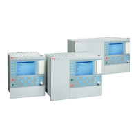
Casing #5 Notes and Rules
1/2 x 19" case A
3/4 x 19" case 1 TRM slot B
3/4 x 19" case 2 TRM slots C
1/1 x 19" case 1TRM slots D
1/1 x 19" case 2 TRM slots E
Selection for position #5.
Mounting details with IP40 of protection from the front #6 Notes and Rules
No mounting kit included X
19" rack mounting kit for 1/2 x 19" case of 2xRHGS6 or RHGS12 A
19" rack mounting kit for 3/4 x 19" case or 3xRGHS6 B
19" rack mounting kit for 1/1 x 19" case C
Wall mounting kit D Note: Wall mounting not
recommended with
communication modules with
fibre connection (SLM, OEM,
LDCM)
Flush mounting kit E
Flush mounting kit + IP54 mounting seal F
Selection for position #6.
Connection type #7 Notes and Rules
Connection type for Power supply module
Compression terminals M
Ringlug terminals N
Connection type for input/output and communication modules
Compression terminals P
Selection for position #7.
Auxiliary power supply #8 Notes and Rules
24-60 VDC A
90-250 VDC B
Selection for position #8.
Human machine hardware interface #9 Notes and Rules
Medium size - graphic display, IEC keypad symbols B
Medium size - graphic display, ANSI keypad symbols C
Selection for position #9.
Analog input system #10 Notes and Rules
No first TRM included X0
Compression terminals A
Ringlug terminals B
First TRM, 6I+6U 1A, 100/220V 6
First TRM, 6I+6U 5A, 100/220V 7
No second TRM included X0
Compression terminals A
Ringlug terminals B
Second TRM, 9I+3U 1A, 110/220V 3
Second TRM, 9I+3U 5A, 110/220V 4
Second TRM, 5I, 1A+4I, 5A+3U, 110/220V 5
Second TRM, 6I+6U, 1A, 110/220V 6 Note: Second TRM 6I+6U must
be selected in C30.
Second TRM, 6I+6U, 5A, 110/220V 7
Second TRM, 6I, 1A, 110/220V 8
Second TRM, 6I, 5A, 5A, 110/220V 9
Second TRM, 7I+5U 1A, 110/220V 12
Second TRM, 7I+5U 5A, 110/220V 13
Selection for position #10.
1MRK 511 361-BEN B
Bay control REC670 2.1 IEC
Product version: 2.1
108 ABB

 Loading...