CP
Communication Processor
RX TX
CP
Communication Processor
RX TX
IL1
IL2
IL3
UL1
UL2
UL3
Io
IL1
IL2
IL3
UL1
UL2
UL3
Io
start L1
start L2
start L3
Release/Trip
Autoreclosure
µC
Control
DSP
Protection,
measurement,
Vo
Analog Input Board
Main Board
Binary Input Output Board(s)
0/4...20mA
Analog Output Board
Analog Input Module
Communication board
0/4...20mA
CAN Eth.
Time Synch.
Binary
inputs
Binary
outputs
A050397
Fig. 3.-4 REF 542plus block diagram
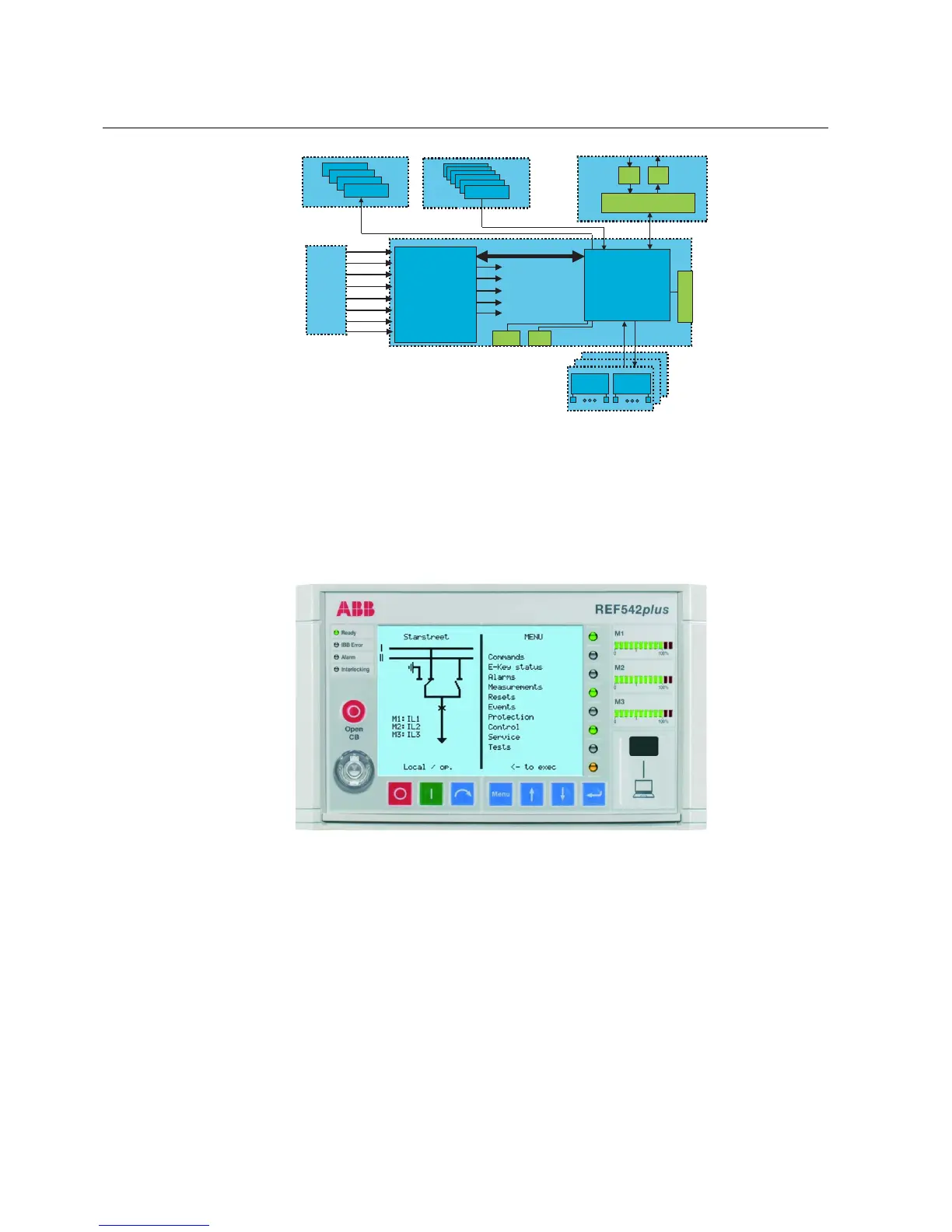
The HMI control unit, as shown in Fig. 3.-5, features a back-illuminated liquid
crystal display (LCD), eight push buttons, several LEDs and an electronic key
interface. The language of the display can be selected by using the related
configuration software tool, which is also used to define the protection and the
control scheme.
A050399
Fig. 3.-5 HMI control unit
The left side of the LCD display is reserved for the single line diagram. The right
side is for plain text visualization such as measurement and protection events. The
LCD backlight is switched off automatically after 20 minutes of inactivity.
The HMI is a complete system for the local management of the switchgear. The
HMI allows the operator to set the protection functions, operate the primary objects,
visualize measurements and events, reset alarms and change the unit working mode.
The HMI includes:
14
REF 542plusREF 542plus
Multifunction Protection and Switchbay Control
Unit
Technical Reference Manual
1MRS755859