65
A070135
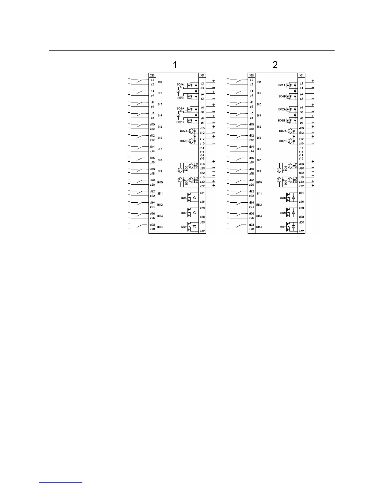
Fig. 8.2.-2 Binary inputs and outputs module Static I/O
1: Standard static I/O
2: Static I/O without control continuity check
In the binary inputs and outputs module BIO3, the trip coil supervision is located in
BO2. Binary outputs BO7 and BO8 are exchange contacts, normally used for
signalling. WD1 is the watchdog contact. In the static output module, there are two
trip coil supervision circuits in BO1 and BO2.
8.3. Typical connection schemes
Some exemplary connection schemes are reported below. Many others are possible.
8.3.1. Generic outgoing feeder
This picture represents the typical connection scheme for outgoing feeders, when
both voltage and current protections are required. There is also a current balance
transformer for earth-fault current sensing. Analog input channel 8 is not used.
Multifunction Protection and Switchbay Control
Unit
Technical Reference Manual
REF 542plusREF 542plus
1MRS755859