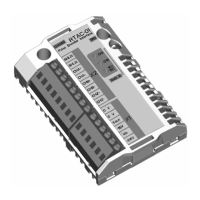
EasyManua.ls Logo

ABB RELION Series User Manual

ABB RELION Series
804 pages
To Next Page IconTo Next Page
Page #1 background imageLoading...
Page #1 background image
RELION® PRODUCT FAMILY
Grid Automation
REC615 and RER615
Technical Manual

Table of Contents

Other manuals for ABB RELION Series

Questions and Answers:

ABB RELION Series Specifications

General IconGeneral
Product SeriesRELION
CategoryControl Unit
Analog OutputsUp to 8
Product TypeProtection and Control IED
Communication ProtocolsIEC 61850, Modbus, DNP3
Input Voltage24-250 V DC / 110-230 V AC
Protection FunctionsOvercurrent, Overvoltage, Undervoltage, Earth fault, Frequency

Summary

RELION® PRODUCT FAMILY

Grid Automation REC615 and RER615 Technical Manual

Technical manual for Grid Automation REC615 and RER615.

Copyright

Trademarks

Mentions registered trademarks of ABB Group and other product names.

Warranty

Information on inquiring about warranty terms from ABB representative.

Disclaimer

Conformity

Section 1 Introduction

This manual

Describes the content and intended use of the technical manual for engineering, installation, commissioning, and service.

Intended audience

Identifies system engineers and installation/commissioning personnel with required knowledge.

Product documentation

Details the product documentation set, including the technical manual and its intended use lifecycle.

Related documentation

Lists related documents such as communication protocol manuals and engineering guides.

Symbols and conventions

Explains warning, caution, information, and tip icons used in the manual.

Document conventions

Defines conventions used in the manual, including abbreviations, menu paths, and formatting.

Section 2 REC615 and RER615 overview

Overview

Introduces REC615 and RER615 relays, their design guided by IEC 61850, and supported communication protocols.

Product series version history

Details the version history of REC615 and RER615 product series, including new configurations.

PCM600 and IED connectivity package version

Specifies supported versions for PCM600 and IED connectivity packages.

Local HMI

Describes the Local Human-Machine Interface (LHMI) components: display, buttons, LEDs, and communication port.

Web HMI

Explains the Web HMI for secure access, its functions, and browser compatibility.

Authorization

Details the four predefined user categories (VIEWER, OPERATOR, ENGINEER, ADMINISTRATOR) with their rights.

Audit trail

Describes the event logging functions for security-related events, storing critical system and relay events.

Communication

Outlines communication protocols like IEC 61850, GOOSE, and Ethernet connections.

Self-healing Ethernet ring

Explains the self-healing Ethernet loop topology, RSTP protocol, and root switch assignment.

Ethernet redundancy

Details network redundancy schemes like PRP and HSR protocols for improved system availability.

Process bus

Describes Process bus IEC 61850-9-2 for Sampled Measured Values transmission.

Secure communication

Explains secure communication for WHMI and file transfer using TLS-based encryption (HTTPS, FTPS).

Section 3 Basic functions

Self-supervision

Details the relay's self-supervision system, covering internal faults and warnings.

LED indication control

Describes the LED indication control using the LEDPTRC function block and its functionality.

Programmable LEDs

Explains the functionality, function block, and signals of the programmable LEDs on the LHMI.

Time synchronization

Details time synchronization methods including internal clock, external sources, and supported protocols.

Parameter setting groups

Explains the support for six setting groups and how to change the active setting group at run time.

Test mode

Describes the operation modes for testing: Normal, IED blocked, IED test, and IED test and blocked.

Application configuration and Test mode

Explains how physical outputs are blocked and how application configuration must be used to block signals.

Control mode

Details how logical nodes under CTRL can be set using Control mode parameter, inherited from Test mode.

Application configuration and Control mode

Explains how physical outputs from control commands are blocked and how application configuration is used.

Authorization

Details the predefined user categories (VIEWER, OPERATOR, ENGINEER, ADMINISTRATOR) with their rights.

Audit trail

Describes the event logging functions for security-related events, storing critical system and relay events.

Communication

Outlines communication protocols like IEC 61850, GOOSE, and Ethernet connections.

Self-healing Ethernet ring

Explains the self-healing Ethernet loop topology, RSTP protocol, and root switch assignment.

Ethernet redundancy

Details network redundancy schemes like PRP and HSR protocols for improved system availability.

Process bus

Describes Process bus IEC 61850-9-2 for Sampled Measured Values transmission.

Secure communication

Explains secure communication for WHMI and file transfer using TLS-based encryption (HTTPS, FTPS).

LEDs

Describes the LHMI LEDs: Ready, Start, Trip, and the 11 matrix programmable LEDs.

Keypad

Explains the LHMI keypad functions for navigation, commands, and interaction.

Fault recorder FLTRFRC

Details the fault recorder function, including capacity, recording period, and data format.

Sensor inputs for currents and voltages

Provides examples on how to define correct parameters for sensors, including correction factors.

Binary input

Explains binary input filtering time and inversion parameters.

Binary outputs

Describes the types of binary outputs: power output contacts and signal output contacts.

Programmable LEDs

Explains the functionality, function block, and signals of the programmable LEDs on the LHMI.

Time synchronization

Details time synchronization methods including internal clock, external sources, and supported protocols.

Parameter setting groups

Explains the support for six setting groups and how to change the active setting group at run time.

Test mode

Describes the operation modes for testing: Normal, IED blocked, IED test, and IED test and blocked.

Control mode

Details how logical nodes under CTRL can be set using Control mode parameter, inherited from Test mode.

Section 4 Protection functions

Three-phase current protection (F)PHxPTOC

Details the three-phase non-directional overcurrent protection, including identification, function block, functionality, and operation principle.

Three-phase directional overcurrent protection (F)DPHxPDOC

Describes the three-phase directional overcurrent protection, covering identification, function block, functionality, and operation principle.

Three-phase thermal protection for feeders, cables and distribution transformers T1PTTR

Explains the thermal overload protection for power lines, its functionality, and operation principle.

Loss of phase, undercurrent PHPTUC

Details the loss of phase and undercurrent protection function, its functionality, and operation principle.

Earth-fault protection

Covers non-directional and directional earth-fault protection functions, including identification, function blocks, and operation principles.

Admittance-based earth-fault protection EFPADM

Describes the admittance-based earth-fault protection for high-resistance earthed, unearthed, and compensated networks.

Harmonics-based earth-fault protection HAEFPTOC

Explains the harmonics-based earth-fault protection for networks with low fundamental frequency components.

Wattmetric-based earth-fault protection WPWDE

Details the wattmetric-based earth-fault protection for unearthed, compensated, and high-resistance earthed networks.

Unbalance protection

Covers negative-sequence overcurrent protection (NSPTOC) and positive-sequence undervoltage protection (PSPTUV).

Phase discontinuity protection PDNSPTOC

Describes the phase discontinuity protection for detecting unbalance situations caused by broken conductors.

Voltage protection

Covers three-phase overvoltage protection (PHPTOV) and three-phase undervoltage protection (PHPTUV).

Residual overvoltage protection ROVPTOV

Details the residual overvoltage protection function, its operation principle, and application.

Frequency protection FRPFRQ

Explains the frequency protection function, including overfrequency, underfrequency, and rate-of-change detection.

Load-shedding and restoration LSHDPFRQ

Describes the load-shedding and restoration function based on underfrequency and rate of change of frequency.

Power protection

Covers three-phase power directional element (DPSRDIR) and multipurpose protection (MAPGAPC).

Protection related functions

Details functions related to protection, including inrush detector, circuit breaker failure protection, and fault locator.

Master trip TRPPTRC

Explains the master trip function as a trip command collector and handler for protection functions.

Fault locator SCEFRFLO

Describes the impedance-based fault location function, its operation principle, and application.

Section 5 Protection related functions

Three-phase inrush detector INRPHAR

Details the three-phase inrush detector function for coordinating transformer inrush situations in distribution networks.

Circuit breaker failure protection CCBRBRF

Explains the circuit breaker failure protection function, activated by trip commands from protection functions.

Master trip TRPPTRC

Explains the master trip function as a trip command collector and handler for protection functions.

Fault locator SCEFRFLO

Describes the impedance-based fault location function, its operation principle, and application.

Section 6 Supervision functions

Trip circuit supervision TCSSCBR

Details the trip circuit supervision function for monitoring the control circuit of the circuit breaker.

Fuse failure supervision SEQSPVC

Explains the fuse failure supervision function used to block voltage measuring functions when secondary circuit failures occur.

Runtime counter for machines and devices MDSOPT

Describes the runtime counter function for calculating and presenting accumulated operation time.

Voltage presence PHSVPR

Details the voltage presence function for indicating voltage presence status of load break switches or circuit breakers.

Section 7 Condition monitoring functions

Circuit-breaker condition monitoring SSCBR

Explains the circuit breaker condition monitoring function for monitoring parameters and generating alarms.

Gas pressure supervision

Describes the gas pressure supervision function for monitoring gas pressure inside the arc chamber.

Section 8 Measurement functions

Basic measurements

Covers fundamental measurement functions like three-phase current, voltage, residual current, sequence components, and frequency.

Three-phase current measurement CMMXU

Details the three-phase current measurement function for monitoring and metering phase currents.

Three-phase voltage measurement VMMXU

Describes the three-phase voltage measurement function for monitoring phase-to-phase and phase-to-earth voltages.

Residual current measurement RESCMMXU

Explains the residual current measurement function for monitoring the residual current of the power system.

Sequence current measurement CSMSQI

Details the sequence current measurement function for monitoring phase sequence currents.

Sequence voltage measurement VSMSQI

Describes the sequence voltage measurement function for monitoring phase sequence voltages.

Disturbance recorder RDRE

Explains the disturbance recorder functionality, including analog and binary signal recording, triggering, and storage modes.

Section 9 Control functions

Circuit breaker control CBXCBR and Disconnector control DCXSWI

Details the control functions for circuit breakers and disconnectors, including operation principle and status indication.

Disconnector position indicator DCSXSWI and earthing switch indication ESSXSWI

Explains the functions for indicating disconnector and earthing switch positions remotely and locally.

Synchronism and energizing check SECRSYN

Describes the synchronism and energizing check function for controlling circuit breaker closing based on synchronization and energizing conditions.

Autoreclosing DARREC

Details the autoreclosing function for circuit breakers, including its operation, protection signal definition, and configuration examples.

Section 10 Power quality measurement functions

Current total demand distortion CMHAI

Explains the current total demand distortion function for monitoring TDD.

Voltage total harmonic distortion VMHAI

Details the voltage total harmonic distortion function for monitoring THD.

Voltage variation PHQVVR

Describes the voltage variation function for measuring short-duration voltage variations in distribution networks.

Section 11 General function block features

Definite time characteristics

Explains the definite time (DT) operation mode and reset properties.

Current based inverse definite minimum time characteristics

Details IDMT curves for overcurrent protection, including user-programmable and standard characteristics.

Voltage based inverse definite minimum time characteristics

Describes IDMT curves for undervoltage protection and user-programmable inverse-time characteristics.

Frequency measurement and protection

Covers frequency measurement, overfrequency, underfrequency, and frequency rate-of-change protection.

Section 13 Protection relay's physical connections

Module slot numbering

Illustrates the module slot numbering (X000 to X130) on the protection relay.

Protective earth connections

Details the protective earth connection requirements, including earth lead size and length.

Binary and analog connections

States that binary and analog connections are described in product specific application engineering guides.

Communication connections

Describes communication connection types: Ethernet and serial.

Ethernet RJ-45 front connection

Details the RJ-45 connector on LHMI for configuration, setting, and IP address settings.

Ethernet rear connections

Explains Ethernet rear connections using RJ-45, LC, and fiber-optic connectors, and supported protocols.

EIA-232 serial rear connection

Describes the EIA-232 serial connection for point-to-point communication, supporting hardware flow control.

EIA-485 serial rear connection

Details the EIA-485 serial connection for daisy-chain bus wiring with half-duplex or full-duplex communication.

Optical ST serial rear connection

Explains the optional optical ST serial connection for loop or star topology, with idle state light indication.

Section 14 Technical data

Dimensions

Provides dimensions (Width, Height, Depth) and weight of the protection relay.

Power supply

Details nominal auxiliary voltage, maximum interruption time, and auxiliary voltage variation.

Energizing inputs

Lists energizing input specifications for current and voltage sensors, including rated values and withstand.

Binary inputs

Details binary input specifications like values, unit, step, default, and description.

Signal output with high make and carry

Specifies output signal characteristics for high make and carry contacts.

Environmental conditions

Lists operating, short-time service, and storage temperature ranges, humidity, atmospheric pressure, and altitude.

Product safety

References LV directive and standards for product safety.

EMC compliance

References EMC council directive and standard for EMC compliance.

Section 15 Protection relay and functionality tests

Electromagnetic compatibility tests

Details EMC test values and references for various disturbances like bursts, ESD, and RF interference.

Insulation tests

Specifies dielectric, impulse voltage, insulation resistance, and protective bonding test values and references.

Mechanical tests

Lists mechanical test requirements for vibration, shock, bump, and seismic tests according to standards.

Environmental tests

Details environmental test conditions including dry heat, cold, damp heat, temperature change, and storage tests.

Product safety

References LV directive and standards for product safety.

EMC compliance

References EMC council directive and standard for EMC compliance.

Section 16 Applicable standards and regulations

Section 17 Glossary

100BASE-FX

Defines 100BASE-FX as an Ethernet standard for LANs using fiber optic cabling.

100BASE-TX

Defines 100BASE-TX as an Ethernet standard for LANs using twisted-pair cabling.

AC

Alternating current.

ACT

Application Configuration tool in PCM600, or Trip status in IEC 61850.

CAT 5

A twisted pair cable type designed for high signal integrity.

CAT 5e

An enhanced version of CAT 5 that adds specifications for far end crosstalk.

CBB

Cycle building block.

COMTRADE

Common format for transient data exchange for power systems, defined by IEEE Standard.

CPU

Central processing unit.

CT

Current transformer.

CTS

Clear to send.

DAN

Doubly attached node.

DC

1. Direct current, 2. Disconnector, 3. Double command.

DCD

Data carrier detect.

DFT

Discrete Fourier transform.

DHCP

Dynamic Host Configuration Protocol.

DNP3

A distributed network protocol developed by Westronic for communication in PLCs and RTU devices.

DPC

Double-point control.

DSR

Data set ready.

DT

Definite time.

EEPROM

Electrically erasable programmable read-only memory.

EIA-232

Serial communication standard according to Electronics Industries Association.

EIA-485

Serial communication standard according to Electronics Industries Association.

EMC

Electromagnetic compatibility.

Ethernet

A standard for connecting computer networking technologies into a LAN.

FIFO

First in, first out.

FPGA

Field-programmable gate array.

FTP

File transfer protocol.

FTPS

FTP Secure.

GFC

General fault criteria.

GOOSE

Generic Object-Oriented Substation Event.

GPS

Global Positioning System.

HMI

Human-machine interface.

HSR

High-availability seamless redundancy.

HTTPS

Hypertext Transfer Protocol Secure.

IDMT

Inverse definite minimum time.

IEC

International Electrotechnical Commission.

IEC 60870-5-101

Companion standard for basic telecontrol tasks.

IEC 60870-5-104

Network access for IEC 60870-5-101.

IEC 61850

International standard for substation communication and modeling.

IEC 61850-8-1

A communication protocol based on the IEC 61850 standard series.

IEC 61850-9-2

A communication protocol based on the IEC 61850 standard series.

IEC 61850-9-2 LE

Lite Edition of IEC 61850-9-2 offering process bus interface.

IEEE 1686

Standard for Substation Intelligent Electronic Devices' (IEDs') Cyber Security Capabilities.

IP

Internet protocol.

IP address

A set of four numbers separated by periods, specifying the location for the TCP/IP protocol.

IRF

1. Internal fault, 2. Internal relay fault.

IRIG-B

Inter-Range Instrumentation Group's time code format B.

LAN

Local area network.

LC

Connector type for glass fiber cable, IEC 61754-20.

LCD

Liquid crystal display.

LE

Light Edition.

LED

Light-emitting diode.

LHMI

Local human-machine interface.

MAC

Media access control.

MCB

Miniature circuit breaker.

MMS

1. Manufacturing message specification, 2. Metering management system.

Modbus

A serial communication protocol developed by Modicon for PLCs and RTU devices.

MV

Medium voltage.

NC

Normally closed.

P2P

1. Personal computer, 2. Polycarbonate.

PC

1. Personal computer, 2. Polycarbonate.

PCM600

Protection and Control IED Manager.

Peak-to-peak

1. Amplitude between max positive and negative values. 2. Measures average from peak values, excluding DC component.

Peak-to-peak with peak backup

Similar to peak-to-peak, but starts on two conditions: peak value > start current or peak value > 2*start current.

PLC

Programmable logic controller.

PPS

Pulse per second.

PRP

Parallel redundancy protocol.

PTP

Precision Time Protocol.

RAM

Random access memory.

RCA

Also known as MTA or base angle. Characteristic angle.

RJ-45

Galvanic connector type.

RMS

Root-mean-square (value).

ROM

Read-only memory.

RSTP

Rapid spanning tree protocol.

RTC

Real-time clock.

RTD

Resistance temperature detector.

RTS

Ready to send.

SAN

Single attached node.

SBO

Select-before-operate.

SCADA

Supervision, control and data acquisition.

SCL

XML-based substation description configuration language defined by IEC 61850.

Single-line diagram

Simplified notation for representing a three-phase power system.

SMT

Signal Matrix tool in PCM600.

SMV

Sampled measured values.

SNTP

Simple Network Time Protocol.

SOTF

Switch onto fault.

ST

Connector type for glass fiber cable.

SW

Software.

TCP/IP

Transmission Control Protocol/Internet Protocol.

TCS

Trip-circuit supervision.

TLV

Type length value.

UTC

Coordinated universal time.

VT

Voltage transformer.

WAN

Wide area network.

WHMI

Web human-machine interface.

Related product manuals