63
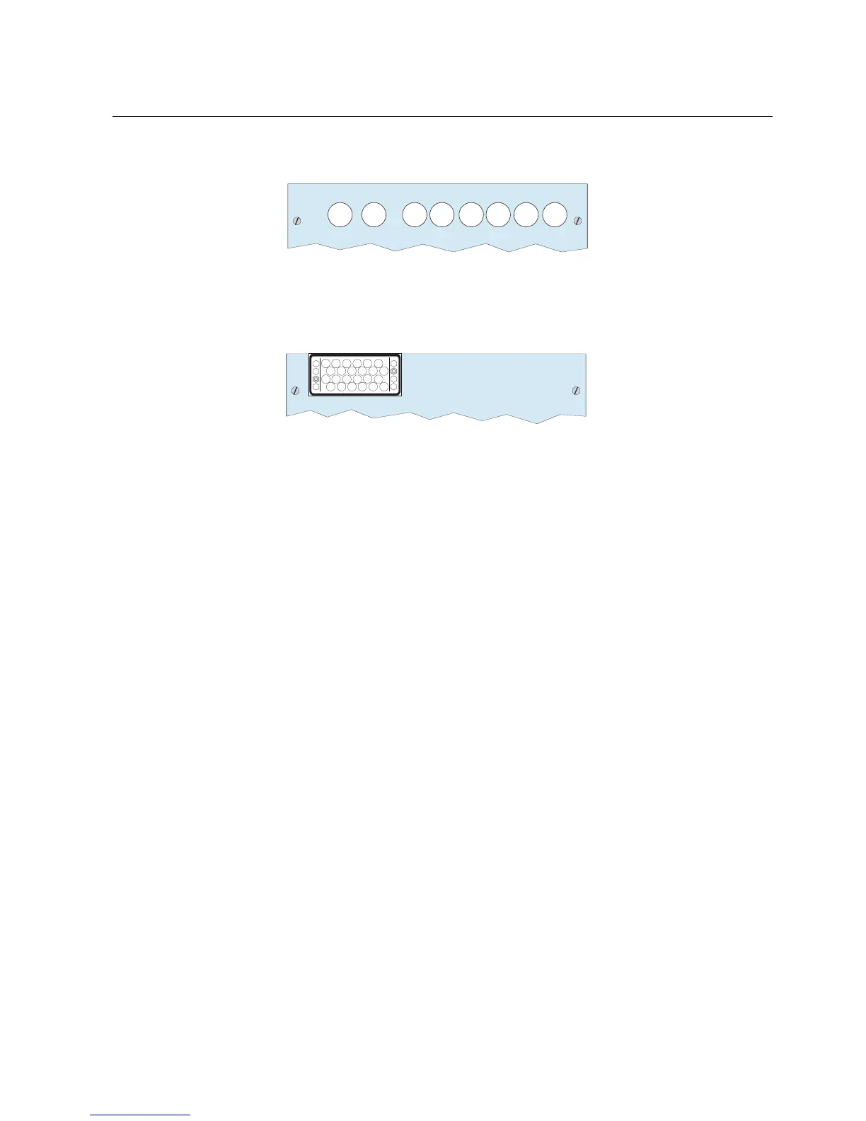
When conventional instrument transformers are in use, the connector looks like in
the Fig. 8.1.-5
X80
X81X83X85X87 X86X88 X84 X82
2
3
6
4
7
11
15 19
20
22
23
24
10
14
16
18
128
1
2
3
5
6
4
7
9
11
13
15
17
19
20
22
23
24
21
10
14
16
18
12
8
A051277
Fig. 8.1.-5 Connector for analog input module sensors and connector for
conventional instrument transformers
8.2. Binary input and output connections
Binary inputs and outputs modules use the following connectors:
*
X20 (inputs), X21 (outputs) for the first module
*
X30 (inputs), X31 (outputs) for the second module
*
X40 (inputs), X41 (outputs) for the third module, available with the wide case
only
The Fig. 8.2.-1 shows the connection diagram for the binary inputs and outputs
module BIO3.
Multifunction Protection and Switchbay Control
Unit
Technical Reference Manual
REF 542plusREF 542plus
1MRS755859