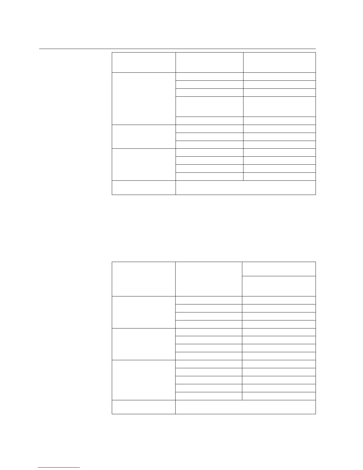
Hardware fixed filter time 1 ms.
Additional filter time can be
configured in software.
6 power outputs (channels
BO 1 to 6)
Maximum operating voltage 250 V AC/DC
Make current 8 A
Load current 6 A
Breaking capacity 1 contact 70 W, 2 contacts in
series 130 W at L/R ≤ 40 ms and
10.000 operations
Operating time 8 ms
2 signal outputs (BO7 and
BO8) and 1 watchdog
output (WD)
Maximum operating voltage 250 V AC/DC
Load current 2 A
Operating time 8 ms
Optional: 1 static output on
BO7
Maximum operating voltage 250 V DC
Make current 1.5 A peak
Load current 0.7 A continuous
Operating time 1 ms
1 coil supervision circuit on
BO2
Coil OK when impedance below 10 Ω
6.4.2. BIO module with static outputs
The technical data for the binary input and output module with static outputs are
listed in Table 6.4.2.-1. This module is full range and covers the complete voltage
range from 48 up to 265 VDC.
Table 6.4.2.-1 Technical data for the binary input and output module with
static outputs
14 inputs (BI 1-14) Auxiliary voltage range: 48 to 265 V DC (Threshold 35 V
DC)
Hardware fixed filter time 5 ms.
Additional filter time can be
configured in software.
3 power outputs (BO1,2 and
þ7)
Operating voltage 48 to 250 V DC
Make current 64 A
Load current 16 A
Operating time 1 ms
4 power outputs (BO3 ... 6) Operating voltage 48 to 250 V DC
Make current 120 A
Load current 31 A
Operating time 1 ms
2 signal outputs (BO8,9)
and 1 watchdog output
(WD)
Operating voltage 48 to 250 V DC
Make current 1.5 A (100 ms)
R
on
1.06 Ω
R
off
40 MΩ
Operating time 1 ms
2 coil supervision circuits on
BO1 and BO2 channels
Coil OK when impedance below 10 kΩ
46
REF 542plusREF 542plus
Multifunction Protection and Switchbay Control
Unit
Technical Reference Manual
1MRS755859