• Abbreviations and acronyms are spelled out in the glossary. The glossary also
contains definitions of important terms.
• Push button navigation in the LHMI menu structure is presented by using the
push button icons.
To navigate between the options, use
and .
• Menu paths are presented in bold.
Select Main menu/Settings.
• WHMI menu names are presented in bold.
Click Information in the WHMI menu structure.
• LHMI messages are shown in Courier font.
To save the changes in nonvolatile memory, select Yes and press
.
• Parameter names are shown in italics.
The function can be enabled and disabled with the Operation setting.
• The ^ character in front of an input or output signal name in the function block
symbol given for a function, indicates that the user can set an own signal name in
PCM600.
• The * character after an input or output signal name in the function block symbol
given for a function, indicates that the signal must be connected to another
function block in the application configuration to achieve a valid application
configuration.
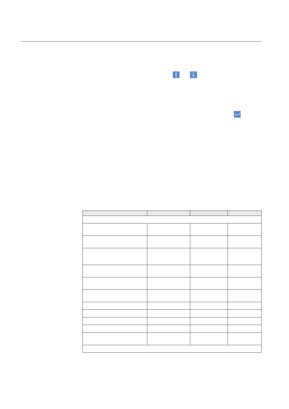
1.4.3 Functions, codes and symbols
Table 1: Functions included in the IEDs
Description
IEC 61850 IEC 60617 ANSI
Protection
Three-phase non-directional
overcurrent protection, low stage
PHLPTOC 3I> 51P-1
Three-phase non-directional
overcurrent protection, high stage
PHHPTOC 3I>> 51P-2
Three-phase non-directional
overcurrent protection,
instantaneous stage
PHIPTOC
3I>>> 50P/51P
Voltage dependent overcurrent
protection PHPVOC I(U)> 51V
Three-phase directional
overcurrent protection, low stage
DPHLPDOC 3I> -> 67-1
Three-phase directional
overcurrent protection, high stage
DPHHPDOC 3I>> -> 67-2
Distance protection DSTPDIS Z< 21, 21P, 21N
Automatic switch-onto-fault logic CVRSOF SOTF SOTF
Fault locator SCEFRFLO FLOC 21FL
Autoreclosing DARREC O -> I 79
Non-directional earth-fault
protection, low stage
EFLPTOC I0> 51N-1
Table continues on next page
Section 1 1MRS756801 E
Introduction
6 630 series
Commissioning Manual