2 IN/RandC/004-EN Rev. A | SM500F | Field mountable paperless recorder
3 Processor board replacement
1. Disconnect the recorder from the power supply.
2. Referring to Fig. 3.1, unlock the door with the key A,
press release catch B and open the door.
3. Referring to Fig. 3.2, remove 6 Torx screws C securing
the door assembly rear cover and remove the rear cover.
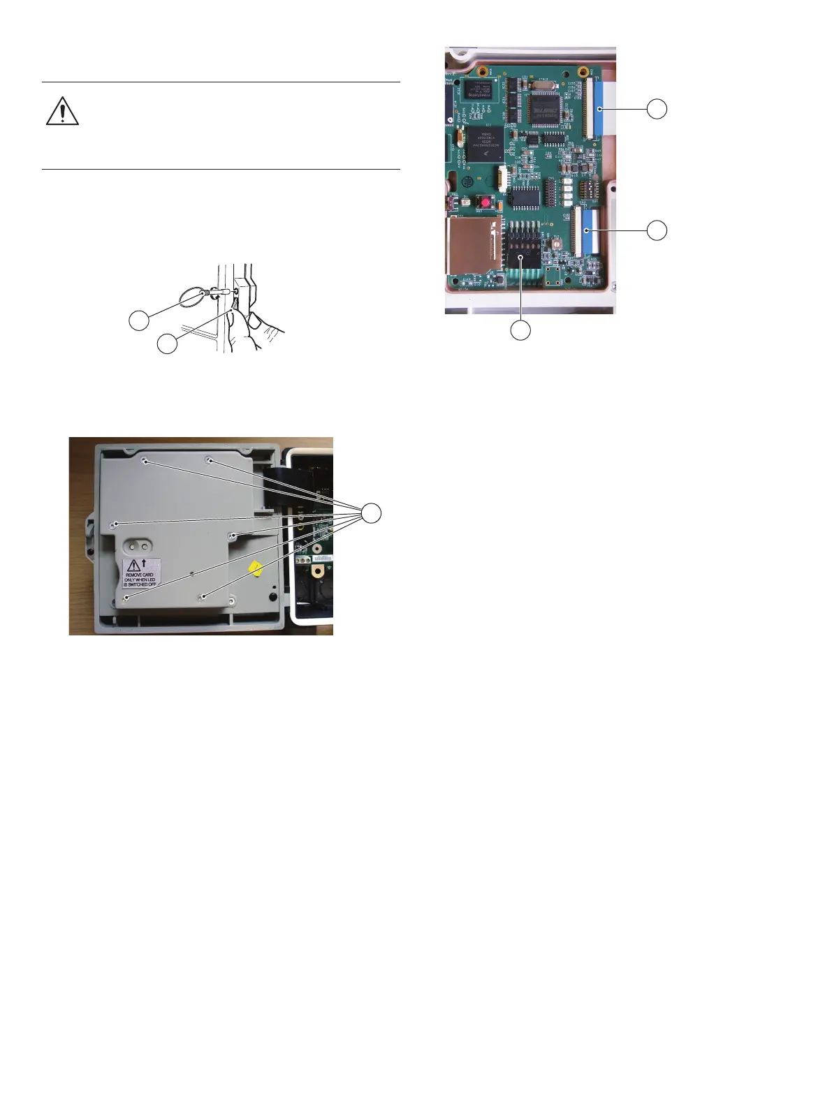
Referring to Fig. 3.3:
4. Disconnect processor board flexi-cable D, display
flexi-cable E and keypad membrane cable F from the
processor board and lift out and discard the processor
board.
5. Position the new processor board in the door housing and
reconnect keypad membrane cable F, display flexi-cable
E and processor board flexi-cable D.
6. Referring to Fig. 3.2, refit the door assembly rear cover and
secure using 6 Torx screws C.
7. Close and lock the door.
8. Restore the recorder's power supply.
NOTICE – Property damage
The recorder is vulnerable to electrostatic damage.
Wear an anti-static strap or place the instrument on
an anti-static workbench.
Fig. 3.1 Opening the door
Fig. 3.2 Removing the rear cover
A
B
C
Fig. 3.3 Disconnecting the processor board
D
E
F

 Loading...


