10
Four protection stages, two signalling and two
tripping, are used in the example described.
Stage 2 produces an alarm signal, if the fre-
quency exceeds the rated frequency, and stage
3, correspondingly, if the frequency falls below
the rated frequency. The selected alarm limits
allow the generator and the turbine to operate
for a long time with the concerned frequency,
without any risk of being damaged.
Should the frequency decrease or increase to a
dangerous level, the relay provides a trip signal.
The protection also includes a blocking input
which can be used for blocking the relay opera-
tion, for instance, during the start of the gen-
erator.
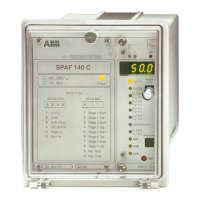
The start values and operate times of the pro-
tection stages and the timers controlling the in-
dividual circuit breakers are shown in Fig. 5.
The designations used in Fig. 5 refer to Fig. 4.
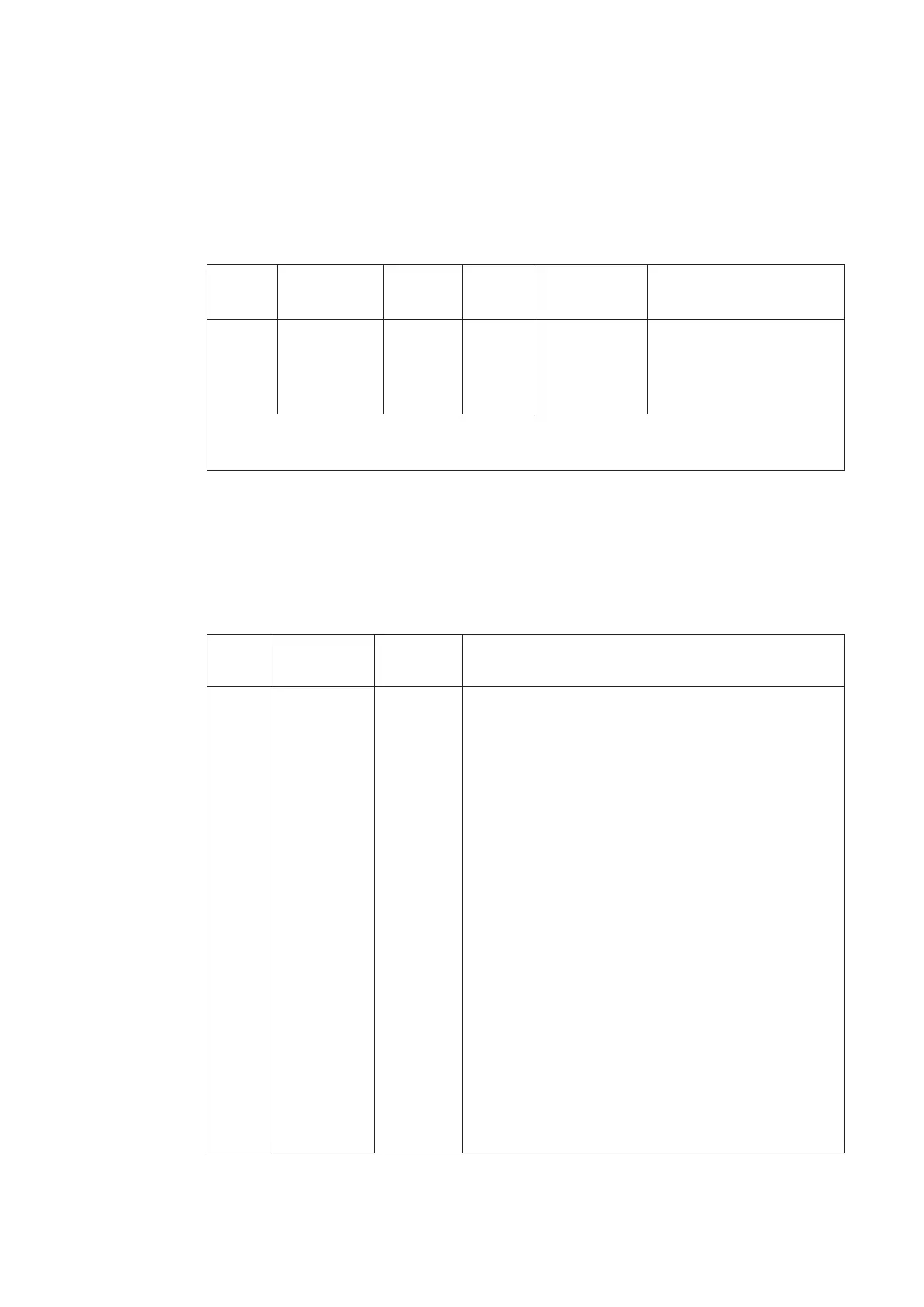
Stage Operate Delay Timer Relay output Function
value (Hz)
1 53.0 0.30 t
1
TS1 Tripping
2 51.5 1.00 t
2
SS1 Overfrequency alarm
3 48.5 1.00 t
3
TS2 * Underfrequency alarm
4 47.0 0.30 t
4
TS1 Tripping
*)The trip contact TS2 is used for underfrequency alarm, because only one trip contact is
required for the protection.
Fig. 5. Setting of the protection stages of frequency relay SPAF 140 C used for the protection of a
generator and a turbine.
In the case described in the example the switches of the frequency relay SPAF 140 C can be set as
follows:
Setting of t, relay module SPCF 1D15
Switch- Serial comm. Checksum Operation
group parameter
SGF1 S84 1 Only frequency function
SGF2 S85 1 Only frequency function
SGF3 S86 1 Only frequency function
SGF4 S87 1 Only frequency function
SGF5 S88 255 Outputs continuously operated
SGF6 S89 2 TS1 connected to LED indicator TRIP
SGF7 S90 0 U
n
= 100 V
SGB1 S91 15 Blocking via external control signal BS1
SGB2 S92 0 External control signal BS2 not in use
SGB3 S93 0 External control signal BS3 not in use
SGB4 S94 0 External control signal BS4 not in use
SGB5 S95 0 External control signal BS5 not in use
SGB6 S96 15 Undervoltage blocking to all stages
SGR1 S97 2 Overfrequency trip signal to trip contact TS1
SGR2 S98 0 Not in use
SGR3 S99 1 Underfrequency alarm signal to signal contact SS1
SGR4 S100 0 Not in use
SGR5 S101 8 Underfrequency alarm signal to trip contact TS2
SGR6 S102 0 Not in use
SGR7 S103 2 Underfrequency trip signal to trip contact TS1
SGR8 S104 0 Not in use
SGR9 S105 0 No recovery function