6
Block diagram
df
dt
>
<
f
>
<
& 1
SGF1/3
SGF1/2
SGF1/1
SGR1/x
SGR2/x
df
dt
>
<
f
>
<
& 1
SGF2/3
SGF2/2
SGF2/1
SGR3/x
SGR4/x
df
dt
>
<
f
>
<
& 1
SGF3/3
SGF3/2
SGF3/1
SGR5/x
SGR6/x
df
dt
>
<
f
>
<
1
SGF4/2
SGF4/1
SGR7/x
SGR8/x
&
(fn-fr)>
(fn+fr)<
SGR9/x
1
2
3
4
5
6
7
8
1
SGF6/1
2
3
4
5
6
7
8
SS1
TS1
SS2
TS2
SS3
TS3
SS4
TS4
S
R
TRIP
SGF5/1
SGF6/2
SGF5/2
SGF6/3
SGF5/3
SGF6/4
SGF5/4
SGF6/5
SGF5/5
SGF6/6
SGF5/6
SGF6/7
SGF5/7
SGF6/8
SGF5/8
t
t
t
t
t
t
t
t
SGF4/3
SGB1/x
BS1
SGB2/x
BS2
SGB3/x
BS3
SGB4/x
BS2
SGB5/x
BS5
U<
SGB6/x
T
#f
∩
#
U
12
1
0
&
t
1
t
1
'
t
2
t
2
'
t
3
t
3
'
t
4
t
4
'
Set
Reset
Count
Start
Count
t
Hardware
System restart
Recovery function
Reset trip indicators
Reset trip indicators
and registers
Settings (main/2nd)
SGF 1...4/4 = 1 Operation indicator latched
Un 100V 110V 115V 120V
Switch
SGF 7/1 0 1 0 1
SGF 7/2 0 0 1 1
Un
SGF 7/3 = 1 Un=
3
Reset
button
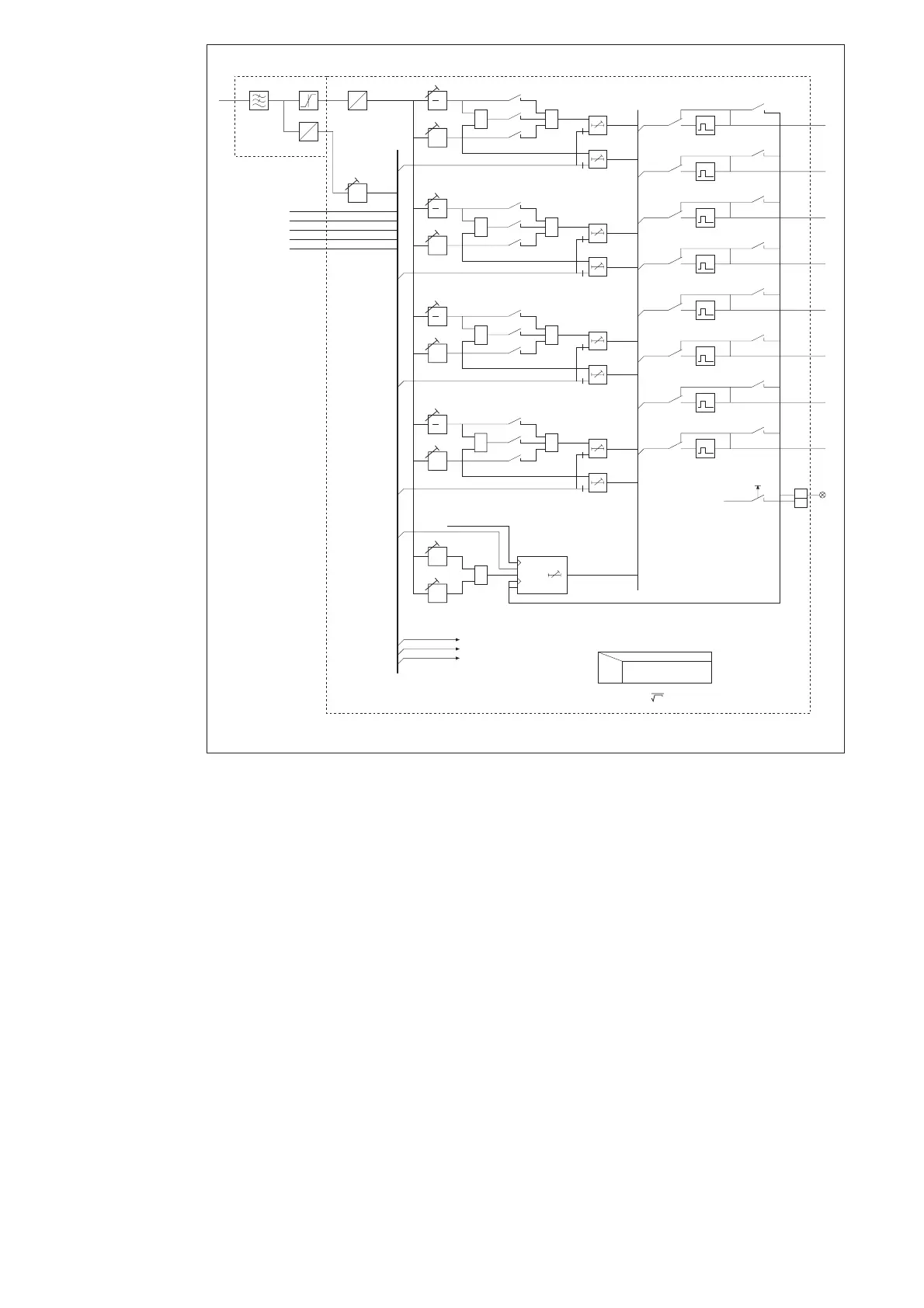
Fig. 2. Block diagram for the combined frequency and rate of change of frequency relay module
SPCF 1D15
U12 Phase-to-phase voltage
BS1...BS5 External control signals
SGF1...SGF7 Switchgroups for relay configuration
SGB1...SGB6 Switchgroup for external control signals
SGR1...SGR9 Switchgroup for output relay matrix
TS1...TS4 Output signals
SS1...SS4
TRIP Red operation indicator
Note!
All input and output signals of the relay mod-
ule are not necessarily wired to the terminals of
each protection relay containing this module.
The signals wired to the terminals are shown in
the signal diagram of the concerned protection
relay.