12 CI/FSS/FSV430/450-EN Rev. D | SwirlMaster FSS430, FSS450 VortexMaster FSV430, FSV450
2.4 Zone 1, 21 - type of protection "flameproof
(enclosure)"
2.4.1 Ex-marking
ATEX
Order code A9
Type examination certificate FM13ATEX0057X
II 2 G Ex d ia IIC T6 Gb/Ga – II 2 D Ex tb IIIC T85 °C Db
(-40 °C < Ta < +75 °C) supply voltage 42 V DC,
Um: 45 V
IECEx
Order code N3
Certificate of conformity IECEx FME 13.0004X
Ex d ia IIC T6 Gb/Ga-Ex tb IIIC T85 °C Db
(-40 °C < Ta < +75 °C) supply voltage 42 V DC,
Um = 45 V
FM approval for USA and Canada
Order code F1
XP-IS (US) CL I/DIV I/GP BCD, DIP CL II, III/DIV I/GP EFG
XP-IS (Canada) CL I/DIV I/GP BCD, DIP CL II, III/DIV I/GP EFG
CL I, ZONE 1, AEx/Ex d ia IIC T6 -40 °C < Ta < +75 °C
TYPE 4X Tamb = 85 °C "Dual seal device"
NEPSI
Order code S1
Ex d ia IIC T6 Gb / Ga
DIP A21 Ta 85 °C
For electrical parameters, see certificate GYJ14.1088X
Power supply
Ex d ia Gb/Ga: U
B
= 12 ... 42 V DC
Switch output
The switch output is designed as an optoelectronic coupler or
a NAMUR contact (in accordance with DIN 19234).
— When the NAMUR contact is closed, the internal
resistance is approx. 1000 Ω.
— When the contact is open, the internal resistance is
> 10 kΩ.
The switch output can be changed over to "optoelectronic
coupler" if required.
— NAMUR with switching amplifier
— Switch output:
Ex d ia: Ui = 45 V
IMPORTANT
The power supply and the digital output must be either only
intrinsically safe or only non-intrinsically safe. A combination of
the two is not permitted.
Intrinsically safe circuits must have potential equalization in
place along the entire length of the cable of the circuit.
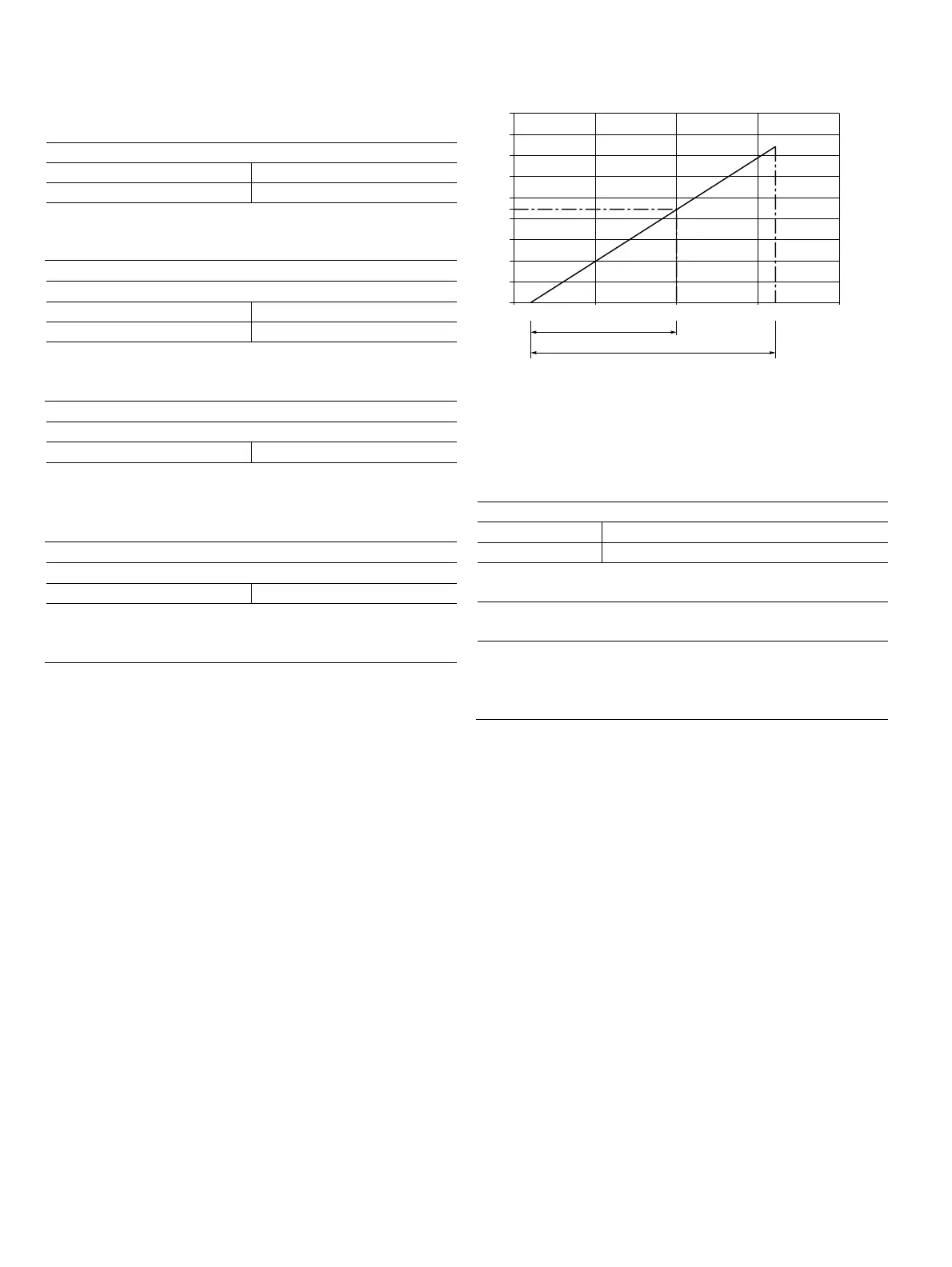
2.4.2 Electrical and temperature data
Fig. 3: Power supply in Zone 1, explosion protection
The minimum voltage U
S
of 12 V is based on a load of 0 Ω.
U
S
Supply voltage
R
B
Maximum permissible load in the power supply circuit,
e.g. indicator, recorder or power resistor.
Power supply / current output / HART output
Terminals PWR/COMM + / PWR/COMM -
U
M
45 V
Zone 1: Ex d ia IIC T6 Gb/Ga
T
amb
= -40 ... 75 °C
Zone 21 Ex tb IIIC T85 °C Db
T
amb
= -40 ... 75 °C
XP-IS (US) CL I/DIV I/GP BCD, DIP CL II, III/DIV I/ GP EFG
XP-IS (Kanada) CL I/DIV I/GP BCD, DIP CL II, III/ DIV I/GP EFG
CL I, ZONE 1, AEx/Ex d ia IIC T6 -40 °C < Ta < +75 °C
TYPE 4X Tamb = 75 °C „Dual seal device“
G11792
10
0
0,2
0,4
0,6
0,8
0,9
1,0
1,2
1,4
1,6
1,8
12
Ex /dXP
U [V]
S
R[k]
B
Ω
30 40 42 50
20
Ex A /iIS
 Loading...


