Do you have a question about the ABB Tmax T8 L5757 and is the answer not in the manual?
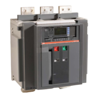
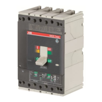
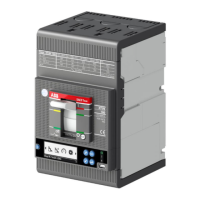
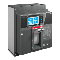
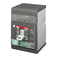
General description of the Tmax T8 circuit-breakers and disconnectors.
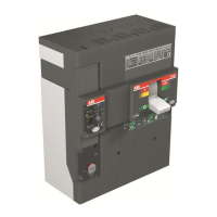
Diagram showing the external front view of the circuit-breaker with numbered components.
Details of the IEC rating plate data for the Tmax T8 circuit-breaker.
Details of the UL rating plate data for the Tmax T8 circuit-breaker.
Requirements for installing the circuit-breaker in a dry, dust-free, non-corrosive environment.
Procedure for installing the flange on the compartment door using self-tapping screws.
Instructions for making power circuit connections using insulated bars.
Schematic illustration of different terminal types available for circuit-breakers.
Examples of busbar layouts for connecting circuit-breakers based on terminal types.
General procedures for putting the circuit-breaker into service, including checks.
Identification and description of circuit-breaker operating and signalling components.
Procedures for manual and electrical closing and opening of the circuit-breaker.
Safety warnings and obligatory procedures before performing maintenance.
Expected mechanical and electrical life cycles of circuit-breakers with different releases.
Frequency of maintenance based on installation environment and usage.
Preliminary steps before starting first-level maintenance, including safety.
General inspection and cleaning procedures for the circuit-breaker.
Inspection and cleaning of circuit-breaker and switchboard connections.
Steps for disassembling the flange and escutcheon plate for maintenance.
Procedure for testing the relay using the SD Testbus2.
Procedure for testing the relay using the EKIP Connect software.
Final checks and reassembly after performing maintenance operations.
Verification of interlock installations between circuit-breakers.
Preliminary steps before starting second-level maintenance, including safety.
General inspection and cleaning for second-level maintenance.
Inspection and cleaning of connections for second-level maintenance.
Steps for disassembling the flange and escutcheon plate for second-level maintenance.
Procedure for testing the relay using SD Testbus2 for second-level maintenance.
Procedure for testing the relay using EKIP Connect for second-level maintenance.
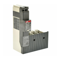
Description of electrical accessories like shunt opening/closing releases and undervoltage releases.
Important safety warnings and precautions for handling the product.
Specific notes regarding dielectric strength tests on release inputs and outputs.
Technical characteristics and compatibility of the three relays: PR232, PR331, PR332.
Overall dimensions for the version with front terminals.
Dimensions of the required compartment for installation.
Specifications for holes to be drilled in the compartment door.
Required insulation distances for installation in metal cubicles.
Critical warnings regarding circuit diagrams and installation.
Description of the operating states illustrated in the diagrams.
Overview of circuit breaker versions for which diagrams are provided.
Information on diagrams applicable to versions without overcurrent release.
Information on diagrams applicable to PR232/P-T8 electronic release versions.
Information on diagrams applicable to PR331/P electronic release versions.
Information on diagrams applicable to PR332/P electronic release versions.
Explanation of symbols and abbreviations used in the circuit diagrams.
Information on incompatible circuit configurations and accessories.
Important notes and explanations related to circuit diagrams and accessory installations.
Circuit diagram for three-pole breakers with electronic releases.
Circuit diagram for four-pole breakers with electronic releases.
Circuit diagram for three-pole breakers with residual current protection.
Circuit diagram for three-pole or four-pole switch-disconnectors.
Diagram illustrating motor operator, opening, closing, and undervoltage release circuits.
Diagram illustrating circuits for signalling contacts.
Diagram of auxiliary circuits for PR331 and PR332 releases.
Diagram of the PR330/V measuring module connections.
Diagram of auxiliary circuits for PR332 with communication module and actuator.
Diagram of the PR120/K signalling module connections.
| Brand | ABB |
|---|---|
| Model | Tmax T8 L5757 |
| Category | Circuit breakers |
| Language | English |