EasyManua.ls Logo

ABB Tmax XT5 - User Manual

ABB Tmax XT5
4 pages
Print Icon
To Next Page IconTo Next Page
Loading...
1
INSTALLATION INSTRUCTIONS
Retrofit of Spectra G-frame with ABB Tmax XT5
breaker Dual Mount (Bolt-On kits)
General
These instructions are applicable to retrofit of Spectra G-frame with ABB Tmax XT5 breaker.
Table 1 lists the parts included in the bolt-on circuit breaker kits for double branch configurations (400A max).
WARNING
Danger of electrical shock or injury. Turn OFF power ahead of the panel board or switchboard before working inside the equipment
or removing any component. Equipment is to be installed and maintained by properly trained and qualified personnel only.
Installation
Numbers in brackets in the following instructions and figures refer to the item numbers in table below.
Item Part Description Qty.



Breaker mounting bracket
 
Mounting Stud


Supplied with breaker
 Left link and Tap assembly
 Middle link and Tap assembly
Item Part Description Qty.
 Right link and tap assembly
 
 
 

Thread Cutting Screw

 
 
Item Part Description
Torque wrench
Retrofit Kit
Required Tools
Below listed tools are required for installation
Table 1. Retrofit kit
Question and Answer IconNeed help?

Do you have a question about the ABB Tmax XT5 and is the answer not in the manual?

Summary

Retrofit of Spectra G-frame with ABB Tmax XT5 breaker Dual Mount (Bolt-On kits)

General

Overview of the instructions' applicability to Spectra G-frame retrofit with ABB Tmax XT5 breaker.

Installation - Retrofit Kit and Tools

Details the parts included in the retrofit kit and lists the required tools for installation.

Installation Steps

Step-by-step guide for installing the breaker, including preparing components and mounting.

Overview

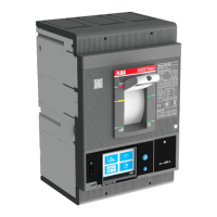
This document provides installation instructions for retrofitting Spectra G-frame with ABB Tmax XT5 breaker Dual Mount (Bolt-On kits). The retrofit kit is designed for double branch configurations, supporting up to 400A.

Function Description

The primary function of this retrofit kit is to enable the installation of an ABB Tmax XT5 circuit breaker into an existing Spectra G-frame panel board or switchboard. This allows for an upgrade or replacement of the existing breaker with the Tmax XT5, ensuring compatibility and proper electrical connection within the panel. The kit includes various components such as carriage bolts, Belleville washers, nuts, breaker mounting brackets, thread-forming screws, mounting studs, Phillips screws, link and tap assemblies (right, middle, and left), phase barriers, filler plates, blankout plates, and screw/washer sets. These components facilitate the mechanical mounting and electrical connection of the new breaker to the vertical bus and bus support rail.

Important Technical Specifications

  • Breaker Type: ABB Tmax XT5
  • Frame Compatibility: Spectra G-frame
  • Mounting Type: Dual Mount (Bolt-On kits)
  • Configuration: Double branch configurations
  • Maximum Current Rating: 400A (for double branch configurations)
  • Fastener Specifications:
    • Carriage bolt: 1/4 - 20 x 1.50"
    • Belleville Washer: 1/4"
    • Nut: 1/4-20
    • Thread-forming screw: #10-32
    • Phillips screw: #6 x 32, 5/16" Length, Pan Head
    • Thread Cutting Screw: #4-20 x 0.375
    • Screw/Washer: steel 10-32X5/16
  • Torque Specifications:
    • Breaker mounting bracket thread forming screw: 30 lb-in.
    • Mounting stud: 18 lb-in.
    • Hex terminal screw: Refer to document 1SDH002011A1002 for specification.
    • Phase barrier Phillips screw: 9 lb-in.
    • Bolted strap connections (carriage bolt assembly) at vertical bus: 65 lb-in.
    • Filler plate thread forming screw: 30 lb-in.
    • Filler plate thread cutting screw: 6.5 lb-in.
  • Insulation Tape Requirement (for unused contacts):
    • Type: UL-recognized 105° C thermoplastic tape (OANZ2, Permacel P-30-105, or 3M66R)
    • Minimum tape thickness: 0.028 inch (achieved with two complete layers of overlapping turns, overlapping greater than one-half of each preceding turn).
  • Panel Interior Dimension: 2.75 inches from the face of the nearest vertical bus to the inner face of the bus support rail.

Usage Features

  • Comprehensive Kit: The retrofit kit includes all necessary hardware for mechanical and electrical integration of the Tmax XT5 breaker.
  • Step-by-Step Installation: The instructions provide a clear, sequential guide for installation, starting from breaker preparation to final assembly and wiring.
  • Modular Link Assemblies: Right, middle, and left link and tap assemblies are provided to connect the breaker poles to the vertical bus, ensuring proper alignment and electrical contact.
  • Phase Barriers: Included to maintain phase separation and enhance safety within the panel.
  • Filler Plates and Blankout Plates: Used for aesthetic finishing and to cover unused spaces in the panel, especially for single breaker installations, maintaining the integrity of the panel's interior.
  • Kirk Lock Compatibility (Optional): The kit supports the pre-assembly and installation of an XT5 Kirk lock mounting kit, allowing for the re-use of an existing Kirk lock from the panel for enhanced security or operational control.
  • Detailed Illustrations: Figures accompany each step, providing visual guidance for component placement and assembly.
  • Safety Warnings: Emphasizes the importance of turning off power and having qualified personnel perform the installation to prevent electrical shock or injury.

Maintenance Features

  • Clear Torque Specifications: Specific torque values are provided for various fasteners, ensuring secure connections and preventing loosening over time, which is crucial for electrical safety and performance.
  • Insulation Guidelines: Detailed instructions for insulating unused strap contact surfaces help maintain electrical integrity and prevent accidental contact or short circuits. This is a critical safety measure for long-term operation.
  • Component Identification: The parts list with item numbers and descriptions facilitates easy identification and replacement of components if needed during future maintenance or troubleshooting.
  • Accessibility Considerations: The instructions note that it may be necessary to remove adjacent circuit breaker modules to access bolted connections at the vertical bus, indicating a design consideration for maintenance access.
  • Documentation Reference: References to external documents (e.g., 1SDH002011A1002 for Hex terminal screw torque) ensure that users can access comprehensive technical data for specific components, supporting thorough maintenance.

ABB Tmax XT5 Specifications

General IconGeneral
BrandABB
ModelTmax XT5
CategorySwitch
LanguageEnglish

Related product manuals