89
6.10 Cable connection
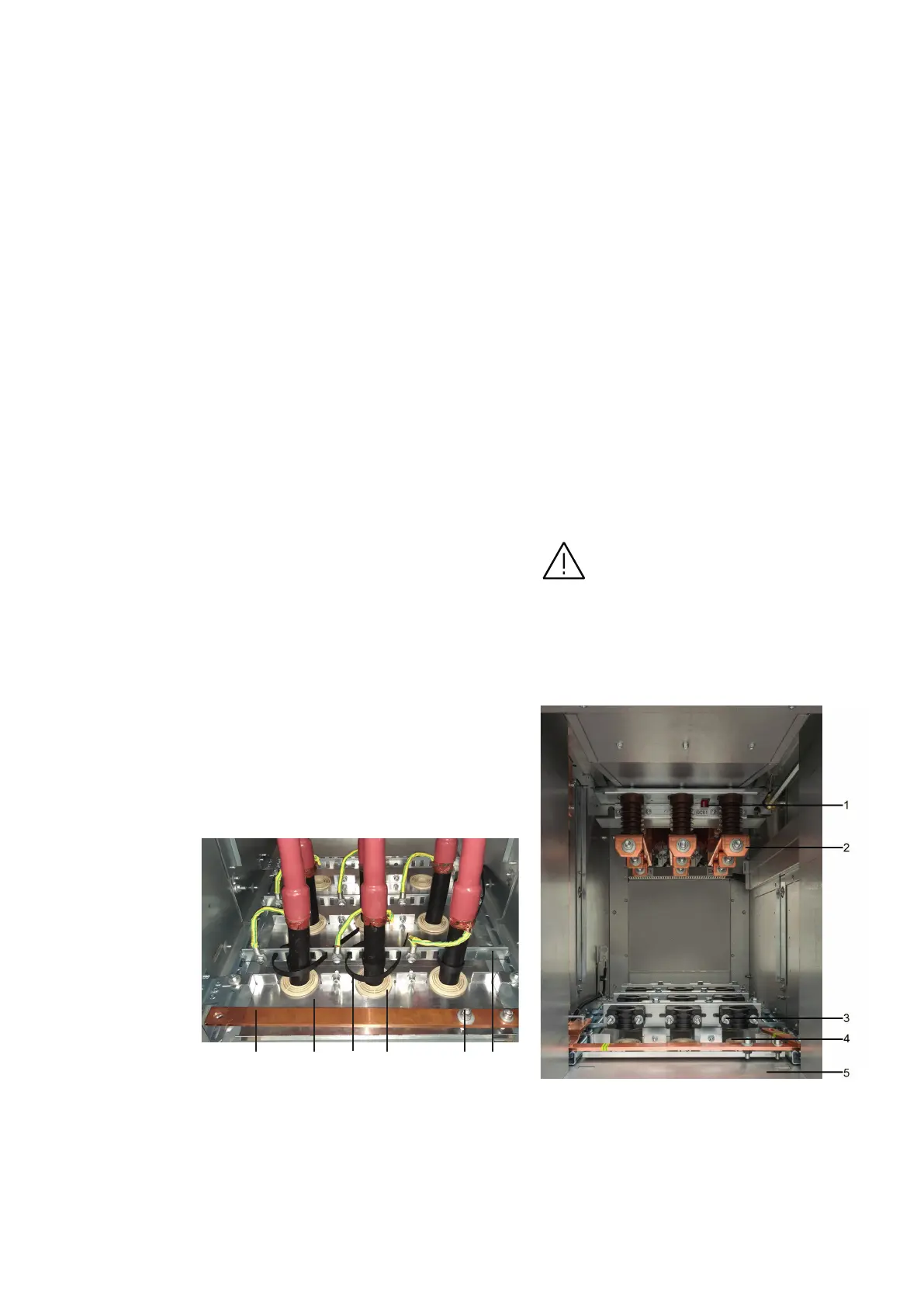
Power cables
The standard method for entry of power cables in
the switchgear is shown in Figure 144. The cables
are conveyed from below through floor covering,
which is divided at the cable entry point.
The cables go through rubber reducer rings,
which can be adapted to the required cable
diameter in a range from 27 to 62 mm. Cables are
fastened in the panel by means of cable holders
(cable ties or cable clamps) mounted on cable
strips, which are part of the panel floor covering.
Cable termination kits are mounted on the cable
cores according to the manufacturer’s
instructions. It is possible to use cable
termination kits from different manufacturers
(e.g. Prysmian, Raychem etc.), but it is necessary
to keep the same length of the cable ends,
including cable termination kits, which is given by
the distance of cable connecting bars from the
panel floor covering.
These bars have different versions, which differ in
their number of parallel cables and the values of
rated and short-circuit currents.
The bars are equipped with holes for M16 screws.
Cable screens wires are connected with cable
strip ensuring earthing as the cable strip is
connected to the ground potential (Figure 144).
It is also possible to place the removable
arrangement of voltage transformers in the cable
compartment. These can be fitted with HV fuses
similar to those in the measuring panel.
Three fixed mounted surge arresters can also be
installed here. In both cases the number of
parallel cables that can be installed is reduced.
Important note:
The cable connection bars are equipped with
holes for M16 screws.
Take care when installing cables so the TR
sensors or environmental sensors are not
damaged where applicable.
—
6. Assembly of the switchgear at site
Figure 144: Figure 145:
1 Main earthing bar
2 Floor cover, split
3 Cable tie
4 Reducer ring
5 Earthing connection pin
6 Cable strip
1 Earthing switch position indicator
2 Cable connection bar
3 Cable clamp
4 Reducer ring
5 Floor cover, split
Partial view into cable connection
compartment with cable ties
View into cable connection
compartment with cable clamps
1
2 54
3
6

 Loading...


