EasyManua.ls Logo

ABB UniSec SDS - Page 26

ABB UniSec SDS
52 pages
Print Icon
To Next Page IconTo Next Page
To Previous Page IconTo Previous Page
Loading...
UNISEC INSTALLATION MANUAL
26
Raised panel position
 

 

Surface flatness of the base
 


 



How to fasten the cubicles


3.5.6 Connecting the main busbars
General warnings and precautions
DANGER
A warning sign is placed on the top plate to
indicate the presence of high voltage under the
roof
CAUTION
It is recommended to mount the busbars starting
from the top of the units
NOTE
Tighten to the correct torque. The torques are
indicated in the “Tightening torques for steel
screws and nuts/bolts” table
NOTE
It is important for the screws to be of the correct
length
The busbar connections are made through the top
openings









Instructions for different types of main busbar
connections





NOTE
Metallic terminal-covers are installed in the
terminal units for 24 kV
NOTE
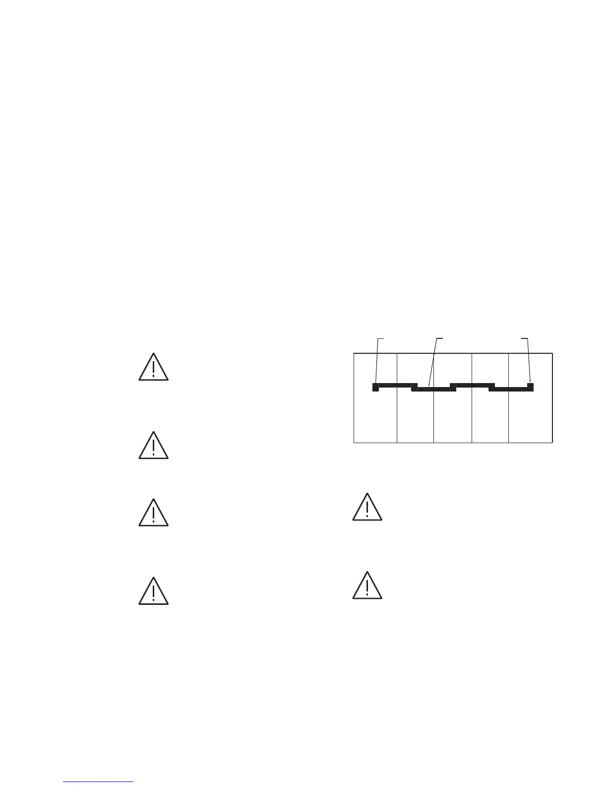
Make sure the busbar spacers are positioned as
shown in the figures below


1
Odd

unit
2


unit
3
Odd

unit
4


unit
Odd

unit



Figure 50. Main busbar connections


Related product manuals